

Exercise 13: Modeling a shaft that can be driven into different tolerance classes
This exercise was carried out with version 27.0 (Vertex 2021).
In this exercise you will learn to
-
To add tolerances to the dimensions of the sketch.
-
To make new configurations for different tolerance needs.
-
Define the configurations to describe the part driven to the nominal, average, or minimum tolerance.
-
Copy a drawing from one configurations to another configurations.
-
To present the dimensions in the sketch for the model drawing.
Functions to be used:
-
Sketching: Drawing lines and diameter dimensioning.
-
Add tolerance markings for sketch dimensions (Dimension Properties > Tolerance).
-
Properties of sketch > Scale.
-
Configurations > New.
-
Configurations > Properties.
-
Drawings > New Drawing.
-
(Drawing >) Copy
-
Insert sketch dimensions to projection (In the properties of projection).
Create a new part
-
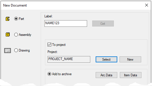
File > New > Part.
-
Enter the label (which is also the name of the model and by default will be the name of the drawing).
-
Enter the archive information by clicking Arc.Data.
-
Select the project where the model will be saved.
-
OK.
-
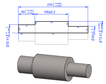
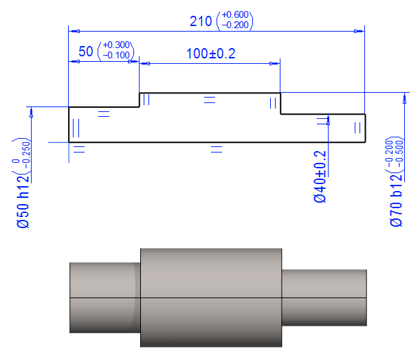
In this exercise, we model a very simple axis that allows us to look at the tolerance of sketch dimensions as well as driving the model to minimum, average, and maximum dimensions.
Create the first feature
-
New Sketch > To horizontal (XY) plane.
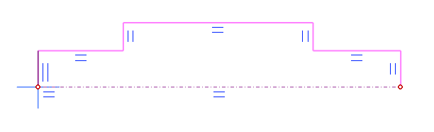
Sketch the shape
-
The function: Two Point Line.
-
Select the line style: Rot.Axis.
-
Start sketching from the origin.
-
-
The function: Polyline.
-
Select the line style: Shape.
-
Start sketching from the origin.
-
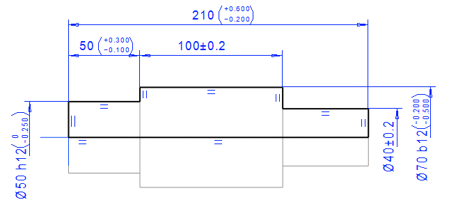
Dimension the sketch
-
Function: Distance.
-
Click the lines to be dimensioned and point the location of dimension. In the figures 1), 2) and 3).
-
Enter the nominal dimension: 50. In the figure 4).
-
Select the type of tolerance: Bilateral. In the figure 5).
-
Enter the upper and lower allowable tolerance: 0.3 and -0.1. In the figure 6).
-
If necessary, use a minus sign (you do not need to enter a plus sign).
-
-
OK. In the figure 7).

-
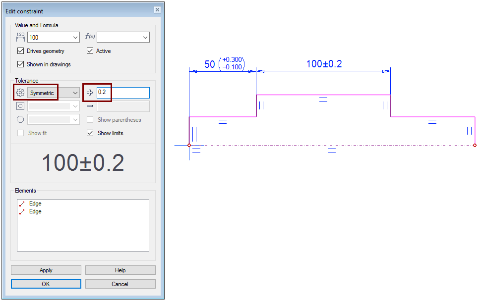
Continue with function: Distance.
-
Point to the next two vertical lines and the location of the dimension.
-
Enter the nominal dimension: 100
-
Select the type of tolerance: Symmetric.
-
Enter the tolerance: 0.2
-
OK.
-
Continue with function: Distance.
-
Click the vertical lines at both ends and the location of the dimension.
-
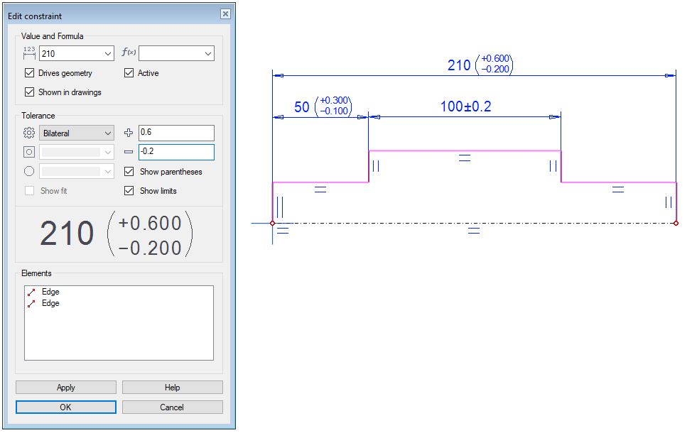
Enter the nominal dimension: 210
-
Select the type of tolerance: Bilateral.
-
Enter the upper and lower allowable tolerance: 0.6 and -0.2.
-
OK.
-
Continue with function: Distance.
-
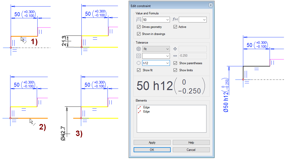
Click to the line on top. In the figure 1).
-
Click to the line of the axis of rotation. In the figure 2).
-
Move the cursor below the axis of rotation.
-
The dimension changes to a diameter dimension.
-
-
Point the location of dimension. In the figure 3).
-
Enter the nominal dimension: 50. In the figure 4).
-
Select the type of tolerance: Fit. In the figure 5).
-
Select tolerance category (from shaft fits): h12. In the figure 6).
-
Here, a "unnecessarily loose" tolerance h12 has been selected to make the dimensional change easier to detect later.
-
You will see that the program calculates the upper and lower difference dimensions.
-
-
OK. In the figure 7).
-
Continue with function: Distance.
-
Click to the line on to and the line of the axis of rotation.
-
Move the cursor below the axis of rotation and point the location of dimension.
-
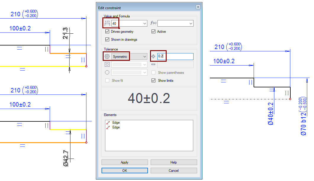
Enter the nominal dimension: 70.
-
Select the type of tolerance: Fit.
-
Select tolerance category: b12.
-
OK.
Close the shape and rotate the sketch to the shaft
-
Skecth a Shape line over the axis of rotation to perform a rotation operation on the sketch.
-
The function: Two Point Line.
-

Operation
-
Boss > Revolve.
-
Angle: 360 (Default).
-
OK.
Set the first configuration to nominal size
-
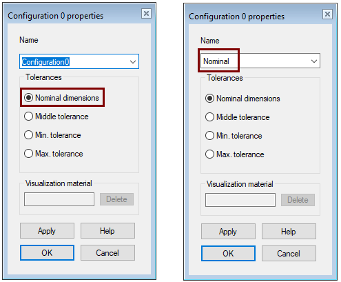
In the feature tree, select: Configurations > 0: Configuration0.
-
Right-click function: Properties.
-
The program opens the dialog Configuration 0 properties.
-
By default, the appearance always describes a nominal dimensions part.
-
-
Enter a descriptive name for the configuration: Nominal.
Create another Configuration and set it to medium size
-
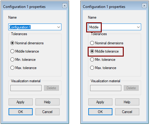
In the feature tree, select: Configurations
-
Right-click function: Add Configuration.
-
The program opens the dialog Configuration 1 properties.
-
-
Enter a descriptive name for the configuration: Middle.
-
Select tolerance: Middle tolerance.
Add a couple more configurations for minimum and maximum tolerances
-
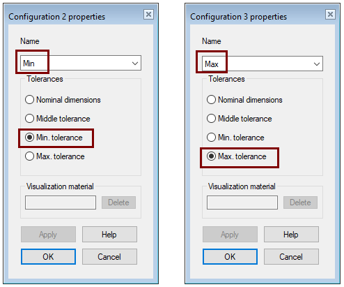
In the feature tree, select: Configurations
-
Right-click function: Add Configuration.
-
Enter a descriptive name for the configurations.
-
Select tolerances: Min tolerance and Max. tolerance.
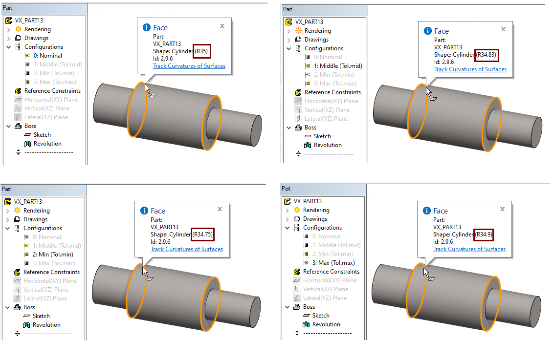
View the dimensions of a part in different configurations
-
Double-click an configuration to activate it.
-
Move the cursor over the cylinder surfaces.
-
The program reports in the tip text, surface information, including radius.
-
-
You can also use the Verify Distance function to view the length of a part.
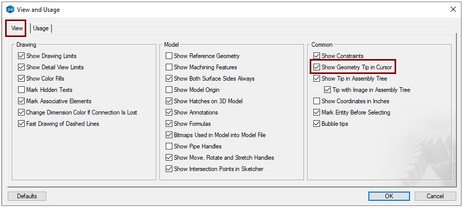
Show (or hide) tip texts with settings:
-
File > User Preferences > Drawings, Models > View-tab > Common group > Show Geometry Tip in Cursor.
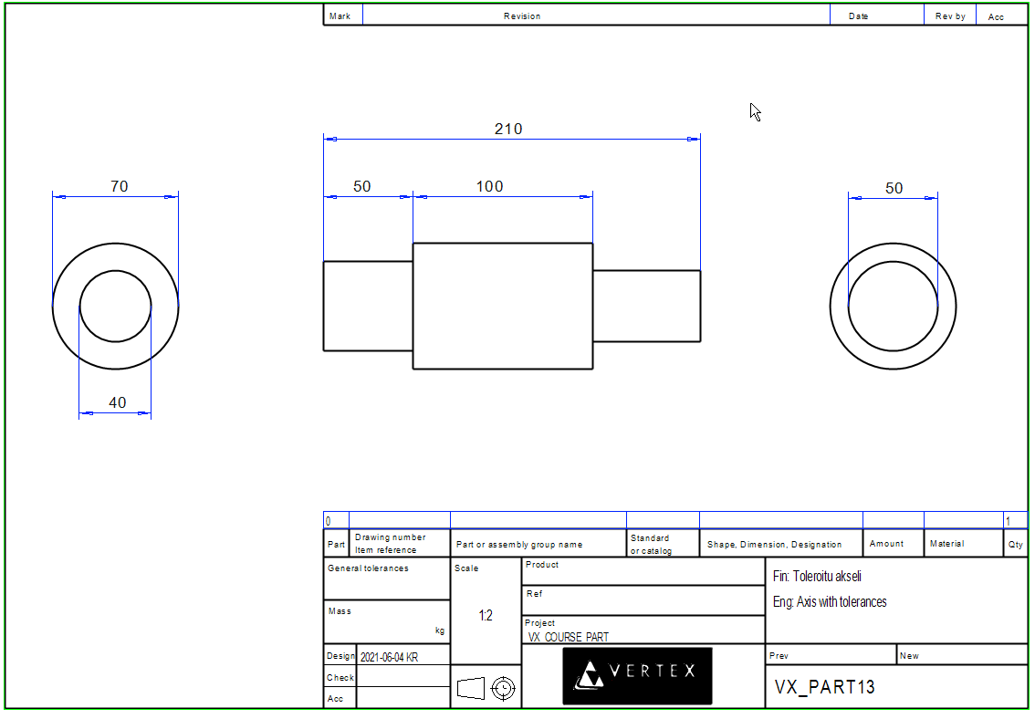
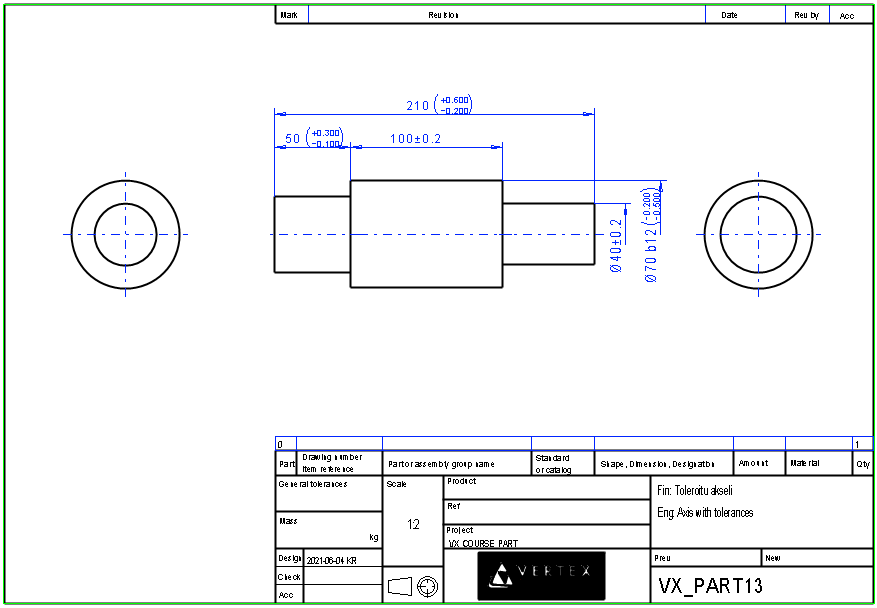
Make a nominal size drawing for the model and dimension it
-
Double-click it to activate the 0-configuration, ie Nominal.
-
Function: Drawings > New Drawing.
-
1:2
-
Sheet: A4_h
-
Projects: Front, left anf right.
-
-
Complete the drawing archive information.
-
Add dimensions.
Save the drawing
-
File > Save or click


-
Remove it from the desktop.
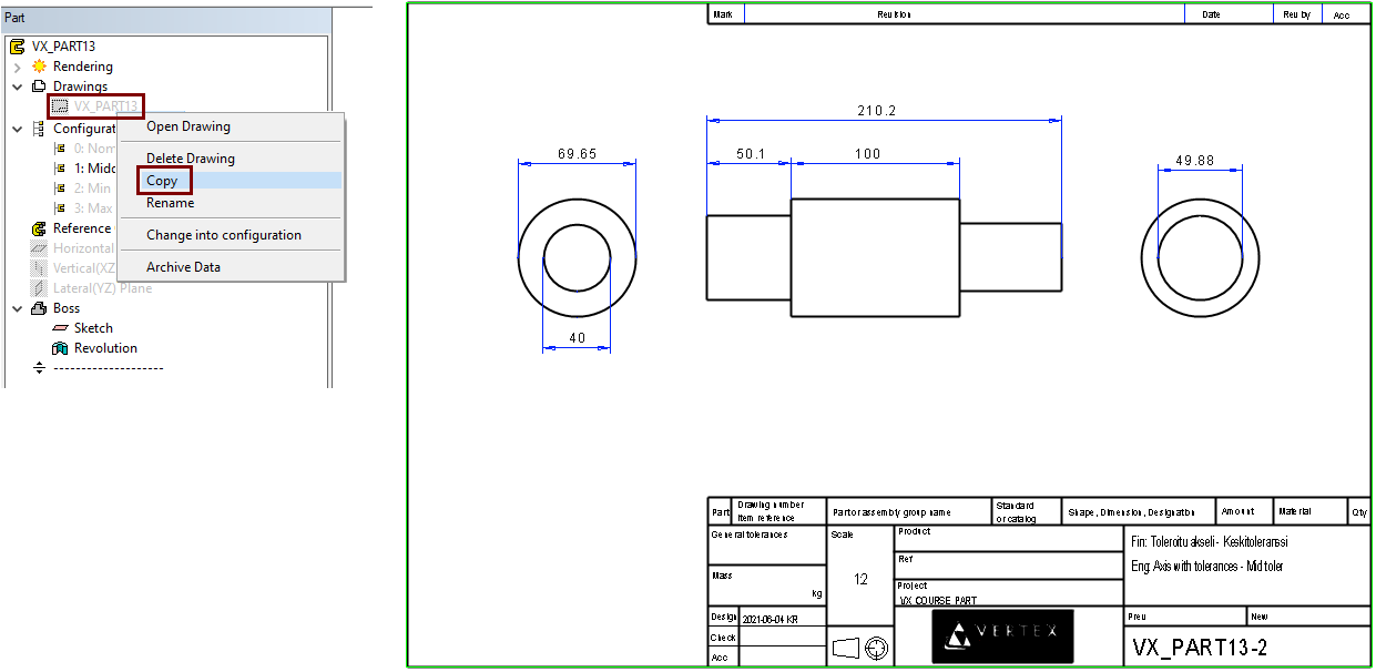
Create a drawing that shows the mean tolerance.
-
Double-click it to activate the 1-configuration, ie Middle.
-
Click on the first drawin.
-
Right-click function: Copy.
-
Complete the drawing archive information.
You can see that some of the dimensions have changed.
-
Some of the changes will be more accurate if you edit the dimension and select precision 0.01 mm instead of the default 0.1 mm.
Save the drawing
-
File > Save or click
-
Remove it from the desktop.
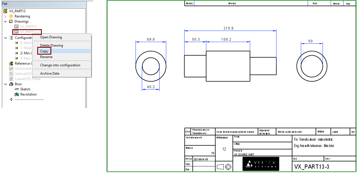
Create a drawing that shows the max tolerance.
-
Double-click it to activate the 2-configuration, ie Max.
-
Click on the secont drawin.
-
Right-click function: Copy.
-
Complete the drawing archive information.
You can see that some of the dimensions have changed.
Save the drawing
-
File > Save or click
-
Remove it from the desktop.
Save the model
-
File > Save or click
Get the dimensions of the sketch for the drawing
The following things should be considered if you want the dimensions in the sketch in the drawing:
-
The dimensions of the sketch are shown in the drawing in the direction in which they are in the model. That is, if you have made a sketch in the XY plane, then these sketches appear in the top projection, but not in the front projection (When you have not yourself shown the direction of the front projection of the model). Of course, the dimensions are also visible in isometric projections.
-
Only the dimensions of one sketch appear in one projection. Of course, you can supplement the dimensions of the sketch with non-driving dimensions (that is, dimensions that do not act as constraints).
-
The scale of the sketch also affects the height of the dimensions in the drawings. For a sketch whose dimensions are to be applied to the projection of the drawing, it is advisable to give the same scale as the drawing.
-
Avoid auto-scales in such sketch.
-
When we made the shaft and the drawing on it, we did not consider importing the dimensions of the sketch into the drawing, so:
-
The sketch scale is Auto (automatically scalable) and must be changed to a fixed scale.
-
The sketch is made in the XY plane, which does not appear in the front projection of the drawing, so we need to correct the situation with one of the following measures:
-
Create a new drawing (Often too big and unnecessary work).
-
Flips the sketch plane upright in the model (In this case, it would work because there are no other history steps in the model that would have been positioned later in the model's basic auxiliary levels).
-
Defines the direction of projection of the drawing from front to top. (This is the fastest way).
-
Open the first (nominal) drawing and remove the dimensions
-
Select the drawing from the feature tree of the model
-
Right-click function: Open Drawing or double-click the drawing.
-
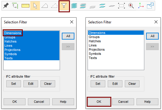
Click Selection Filter from the tool strip.
-
The Selection Filter dialog opens.
-
-
Select Dimensions to deselect other options.
-
OK.
-
Fence drawing projections.
-
You will see that only the dimensions will be selected.
-
-
Press the Delete key or delete the dimensions with the right-click function: Delete.
Include all elements in the selection filter.
-
Click Selection Filter from the tool strip.
-
The Selection Filter dialog opens.
-
-
Select All.
-
OK.
Try to get the dimensions of the sketch for the projection
-
Select projection: Front.
-
Right-click function: Properties or double-click the projection.
-
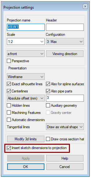
The program opens the dialog Projection settings.
-
-
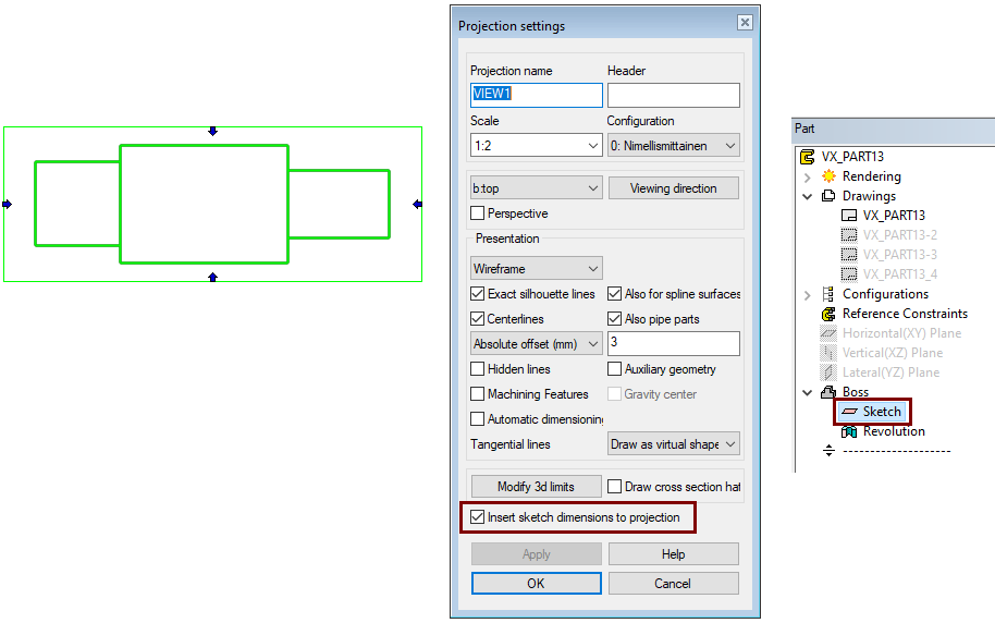
Select Insert sketch dimensions to projektion.
-
The program opens the model.
-
-
In the feature tree, double-click the sketch whose dimensions you want to project.
-
The program returns to the Projection Settings dialog.
-
-
OK.
However, the dimensions do not appear in the drawing.
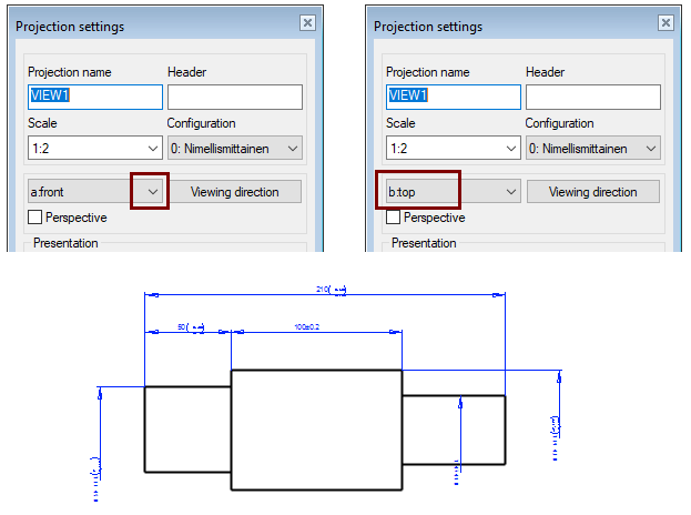
Edit the projection direction
-
Double-click the projection.
-
The program opens the dialog Projection settings.
-
-
Change the selection from front to top.
-
OK.
Now the dimensions appear in the projection, but they are in a vague size.
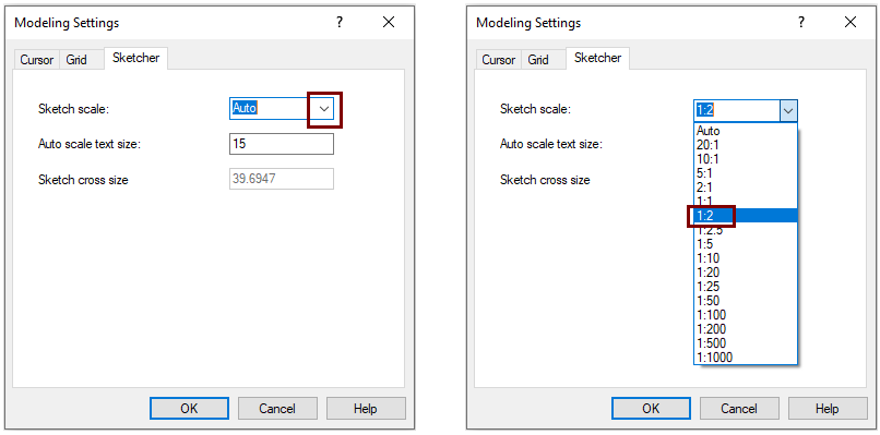
Edit the scale of the sketch
-
Activate the model
-
Double-click the sketch to edit it.
-
Right-click function: Properties.
-
The program opens the dialog: Modeling Settins.
-
-
Choose a sketch scale: 1: 2 (or the scale where your drawing is).
-
OK.
Drag the dimensions to the location where you want them to be in the drawing as well.
-
Exit sketch:
Activate drawing
-
Use the Ctrl Tab key combination to change the activity of the model window to the drawing window.
-
Update the drawing.
-
If the centerlines were missing from the projections (As in the exercise sample drawing), select Centerlines to add them through the projection properties.
You can edit the dimension of the sketch in the drawing.
-
Double-click to dimension (shown in the drawing).
-
The program opens a sketch of the 3D model for editing.
-
-
Double-click the dimension you want to change and give it a new value or a new tolerance
-
At the same time, you can edit all the other dimensions of the sketch and drag them to their new locations.
-
Exit the sketch to the drawing with the right-click function:
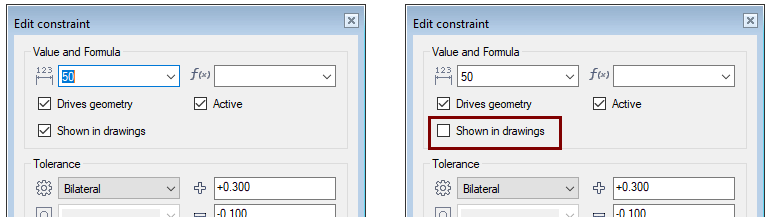
In the drawing, you cannot delete a dimension that has been added to a sketch and is visible in a drawing. Dimensions unnecessary in the drawing must be defined in the sketch as dimensions that do not shown the drawing.
-
Double-click to dimension (shown in the drawing).
-
Double-click to dimension (shown in the drawing).
-
-
Double-click the dimension that you want to hide in the projection of the drawing
-
Deselect Shown in the drawing.
Save the drawing and the model
-
File > Save or click