

Exercise 12: Watering Can
KESKEN
This exercise was carried out with version 27.0 (Vertex 2021).
In this exercise you will learn to
-
Create a new sketch plane using three points assigned to geometry.
-
To create a part using cross-sections (by Lofting - Skinning).
-
To control the lofting function with tangential control curves.
-
To visually analyze the fluidity of surfaces.
Functions to be used:
-
We review sketching tools.
-
Sketching: New Sketch > 3D Sketch
-
Operation: Guide curve, Cross Section.
-
Lofting (The action appears in the feature tree as Skinning).
-
Shell.
-
Rendering > Shaded > Zepra.
Create a new part
-
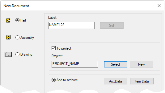
File > New > Part.
-
Enter the label (which is also the name of the model and by default will be the name of the drawing).
-
Enter the archive information by clicking Arc.Data.
-
Select the project where the model will be saved.
-
OK.
-
Create the first feature
-
New Sketch > To vertical (XZ) plane.
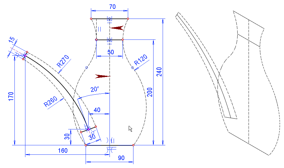
Sketch the shape
-
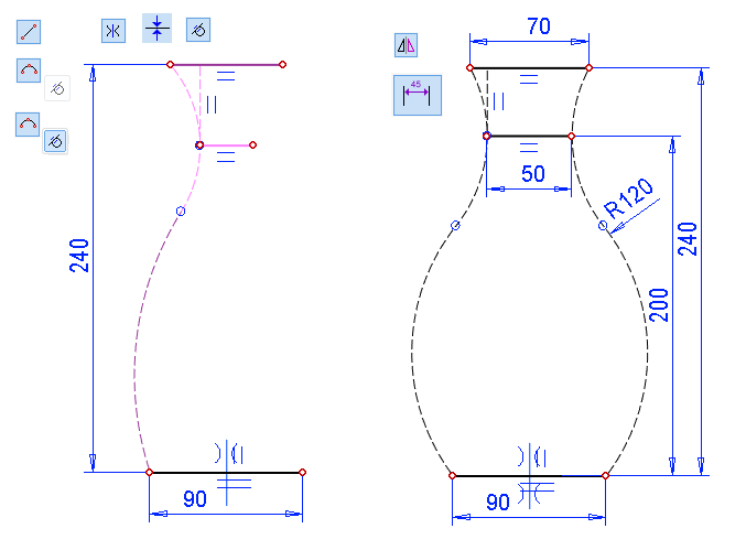
First, add horizontal lines (style: Shape) and place them symmetrically on the center cross.
-
The function: Two Point Line.
-
Symmetry constraint.
-
Conincident constraint. (Bottom line and center cross).
-
-
Then add a vertical line (style: Construction) between the top two horizontal lines at the end of the lower horizontal line.
-
Add two tangential arcs to each other according to the shape of the frame. (style: Guide)
-
Align the upper arc with the end of the middle horizontal line (Coincident constraint).
-
Place the upper arc tangential with the vertical control line (Tangential constraint).
-
Now add the main dimensions, height: 240 and width of the base 90.
-
Mirror the arches.
-
Dimension the sketch.
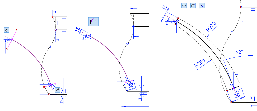
Continue sketching, sketch the head arc and Guide line of the nozzle
-
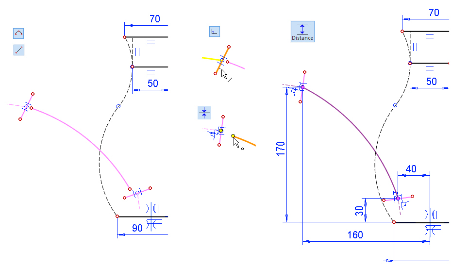
Sketch an arc (style: Shape).
-
Sketch two lines near the end of the arc (style: Shape or Guide).
-
Sketch two lines that start in the middle of the guide line (style: Construction).
-
Add a Perpendicular constraint between the shape line and the construction line.
-
Note the lines at both ends of the arc.
-
-
Add a coincident constraint between the end of the shape line and the end of arc.
-
Note the lines at both ends of the arc.
-
-
Add distance constraint
-
This stabilizes the position of the arc, which could be altered by the tangential constraint.
-
-
Add tangential constraint between the construction lines and the arc .
-
Note the lines at both ends of the arc.
-
-
Define the length of the lines (Dimension constraint).
-
15 and 30 mm like in the figure.
-
-
Sketch two arcs (Acr with Tree Points, without tangentiality).
-
Add radius constraints.
-
260 and 270 mm like in the figure.
-
-
Add the angle constraint: 20, between the center cross of the construction line.
-
Skecth the symmetry axis with two line segments (style: Guide).
-
The beginning and end of the lines at the center of the horizontal lines.
-
This is because in the next sketch we need a point to the center of the second upper line.
-
-

Operation
-
Guode Curve
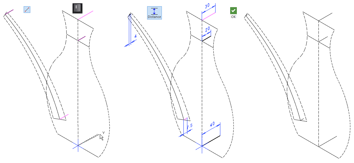
Sketch guide lines to control the width of the watering can
-
Right-click function: New Sketch > 3D Sketch
-
Skecth five line segments locked in the Y-axis direction.
-
Lock with either the cursor Y orientation or the I key.
-
-
Dimension the sketch.
-
At the end of this exercise, a model is presented with a sketch also in the lateral (YZ) plane.
-
In this sketch, those three lines on the centerline of the can have been replaced by symmetrical lines and additional guide lines are included for the lateral shape of the watering can.
-
However, a 3D sketch is needed to position the nozzle cross sections.
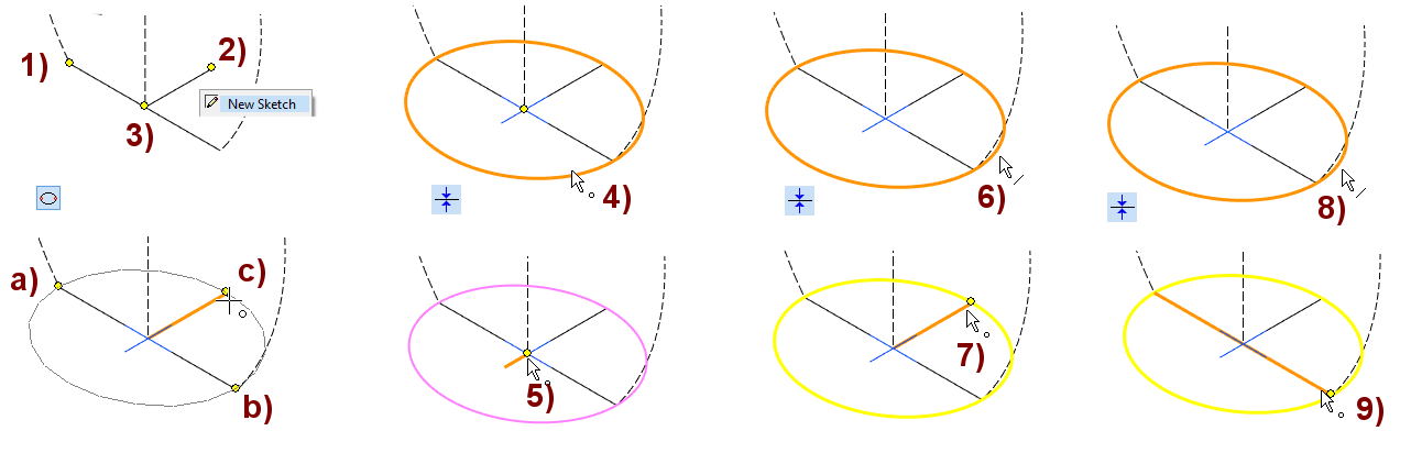
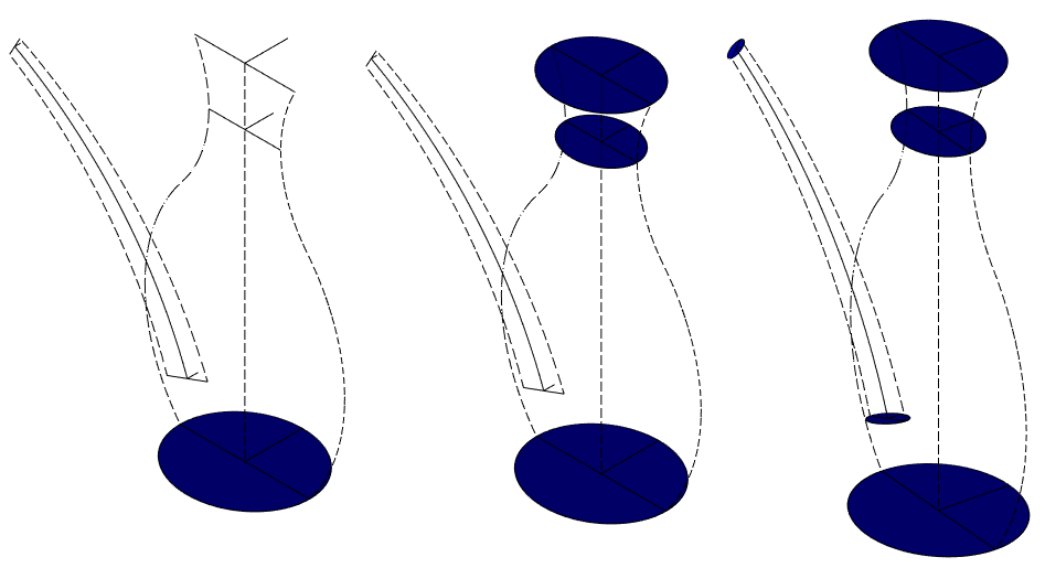
Model the shape of the base, the ellipse.
Define the sketch level
-
Select three points to define the draft level. Lastly, select the point that will become the origo of the sketch.
-
In the figure, points 1), 2) and 3).
-
-
Right-click function: New Sketch.
Sketch the shape
-
The function: Ellipce.
-
Click the point on the main axis of the ellipse, in the figure a) and b), and then the point defining the width of the ellipse, in the figure c).
-
If there was no need to edit the first sketch, then this would be enough. However, three coincident constraint are added that bind the ellipse to the previous control geometry:
-
The center of the ellipse and the end point of the guide line, in the figure 4) and 5).
-
Ellipse line and endpoint of guide line, in the figure 6) and 7).
-
Ellipse line and endpoint of guide line, in the figure 8) and 9).
-
-
Operation
-
Cross Section.
Model the following four cross sections.
-
Define the sketch level in the same way as above.
-
Sketch the ellipse in the same way as above.
Save the model
-
File > Save or click


-
Before lofting experiments, it is advisable to save the model in order to always return to the situation where the cross sections are ready.
-
Otherwise, the author of the self-study material often recommends the save the model, as they are good insurance against possible modeling mistakes during practice.
The edge curve of the cross-sections must match exactly the guide curves used to guide the coating.
-
For example, a control curve, which penetrate a cross-section cannot be used to control a lofting.
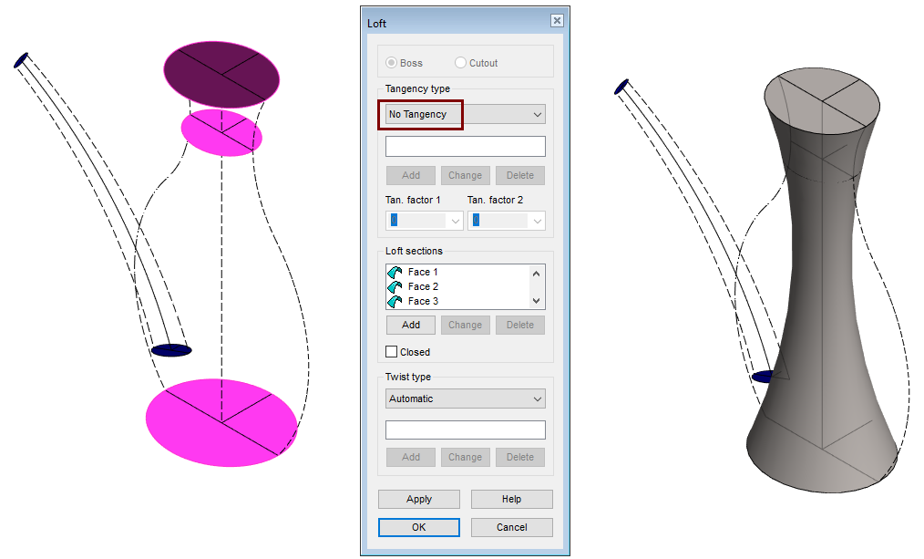
Model the body using cross sections
-
Select three horizontal cross-sections (representing the watering can body).
-
Right-click function: Lofting > Boss.
-
Accept the default values for the experiment, i.e. Tangency type: No Tangency.
-
-
OK.
You will see that the shape is not the same as the body is thought of.
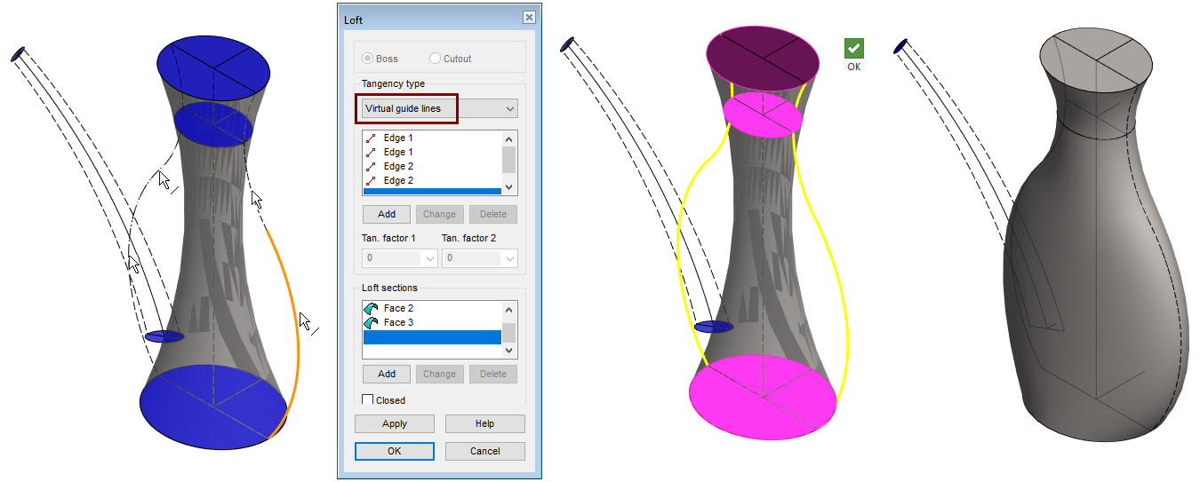
Modify the skinning (Lofting) by including control curves
-
Click the Skinning, in the feature tree, or select a face from the part (in this case, all faces are valid.
-
Right-click function: Edit operation.
-
Change tangency type: Virtual guide lines.
-
Click the guide lines (four yellow arc in the figure).
-
OK. (Add lines to Loft dialog).
-
-
OK.
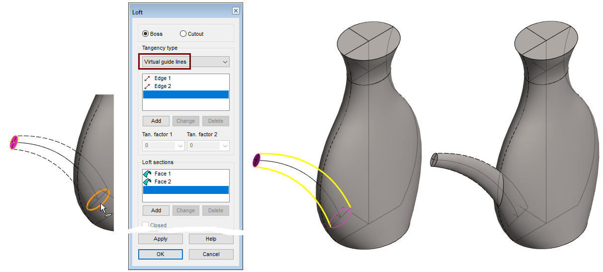
Model the nozzle using cross sections
-
Select two cross-sections (representing the watering can nozzle).
-
Right-click function: Lofting > Boss.
-
Select tangency type: Virtual guide lines.
-
Click the guide lines (two yellow arc in the figure)
-
OK. (Add lines to Loft dialog).
-
-
OK.
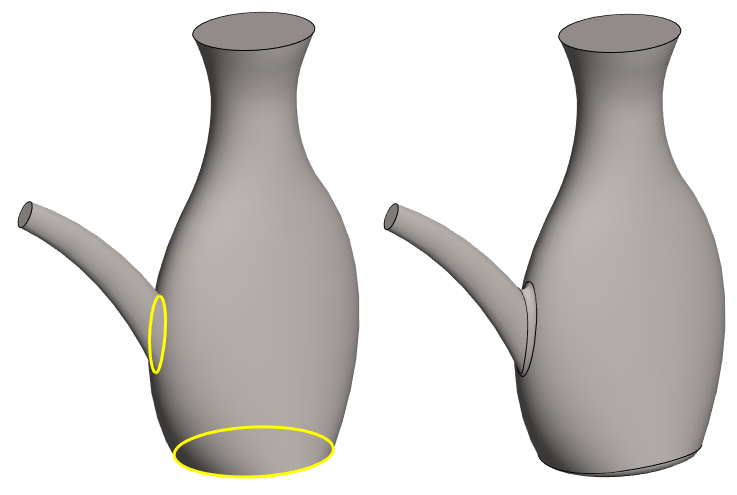
Add rounding between the nozzle and the body and to the bottom of the watering can.
-
Click lines. (yellow lines in the figure).
-
Right-click function: Add Round/Bevel > Round.
-
Enter the radius: 5.
-
OK.
For some reason, the program does not allow a greater radius for this part than 5.5mm.
-
At the end of the exercise, look at a watering can modeled with other dimensions, where rounding is possible up to 10mm.
Create the hollow part
TÄMÄ JÄI KESKEN, KOSKA KOVERRUS EI ONNISTUNUT
-
KOVERRUS NÄYTTI ONNISTUVAN JOS PYÖRISTYKSET JÄTETTIIN POIS NOKAN JA RUNGON VÄLISTÄ
Save the model
-
File > Save or click
Further processing of the model (These are presented in Exercise 5 "Drawing on model")
You can add a material item to the model with the right-click function Item Data.
-
These will also appear in the parts list of the model drawing.
You can create a drawing for the model:
-
In the feature tree, select Drawings.
-
Right-click function: New Drawing.
Download the XX here