

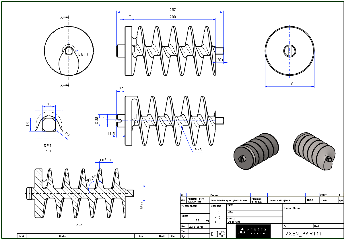
Exercise 11: Grinder Screw
This exercise was carried out with version 27.0 (Vertex 2021).
In this exercise you will learn to
-
To model the spiral.
-
To sweep the cross section along the spiral curve.
-
Accurately position the sketch on the cylindrical surface.
Functions to be used:
-
Spiral.
-
Cross Section.
-
Sweep.
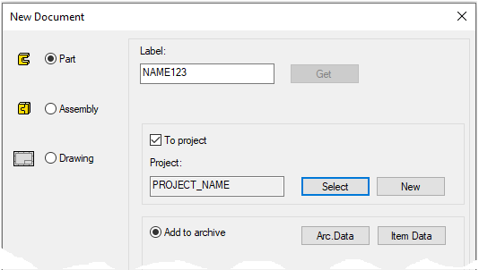
Create a new part
-
File > New > Part.
-
Enter the label (which is also the name of the model and by default will be the name of the drawing).
-
Enter the archive information by clicking Arc.Data.
-
Select the project where the model will be saved.
-
OK.
-
Create the first feature
-
New Sketch > To horizontal plane.
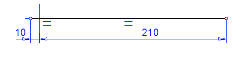
Sketch the shape
-
Sketch a line.
-
Add a coincident constraint between the line and the horizontal line of the center cross.
-
Dimension the beginning of the line 10 mm from the center cross to the left.
-
Dimension the end of the line 210 mm from the center cross to the right.
-

Operation
-
Guide Curve.
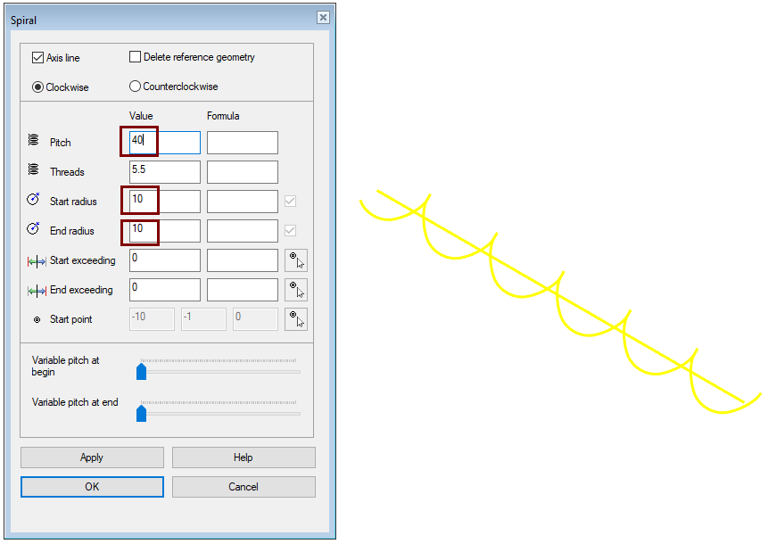
Create a spiral
-
Select the line.
-
Right-click function: Add Spiral.
-
Enter values in the Spiral dialog.
-
Pitch: 40.
-
Start radius: 10.
-
End radius: 10.
-
Accept other fields by defaul.
-
-
OK.
-
If you enter the Pitch, the program counts the number of Threads.
-
If you enter the Threads, the program counts the number of Pitch.
-
You can also enter or select start and end crossings. Positive and negative values work.
-
You can create a spiral clockwise or counterclockwise.
-
With the Axis line option, the program draws a axis line of spiral. This is used when a cylinder or cone is selected as the spiral reference geometry.
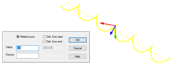
Model the cross section of the screw thread
-
Click the spiral line.
-
Right-click function: New Sketch
-
Accept the relative position proposed by the program: 0.5.
-
OK enters sketch mode.
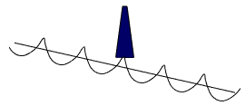
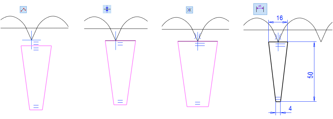
Sketch a cross section
-
Polyline.
-
Add a coincident constraint between the upper horizontal line and the horizontal line of center cross.
-
Add a symmetry constraint for oblique lines with respect to the vertical line of center cross.
-
Dimension the sketch.
-
Operation
-
Cross Section
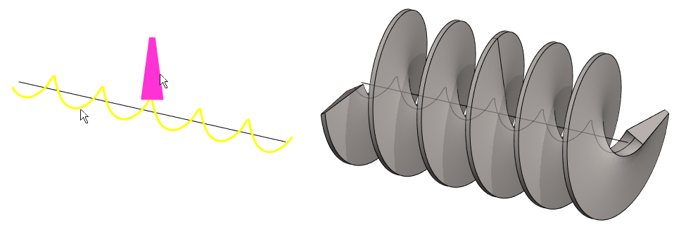
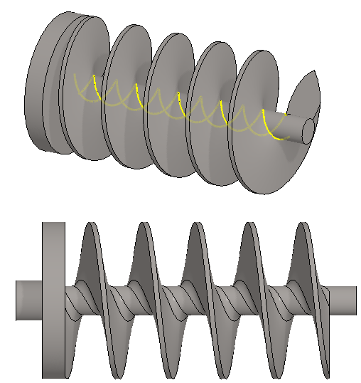
Model the thread using the guide line and cross section
-
Click the line and the cross section (Remember Ctrl key).
-
Right-click function: Sweep > Boss.
-
Accept the dialog defaults.
-
OK.
Cut the right end of the spiral flat
-
New Sketch > To horizontal plane.
Sketch the shape
-
Sketch a rectangle.
-
Dimension the left edge of the rectangle from center cross: 200.
-
It is sufficient that the rectangles extend beyond the existing edges of the part, but you can also add dimension constraints to them.
-
This would be mandatory if the part was driven by dimension table.
-
Here, the horizontal lines of the rectangle are placed symmetrical with the horizontal line of the central cross.
-
-
Operation
-
Cutout > Extrude.
-
In Both Directions
-
Thru All
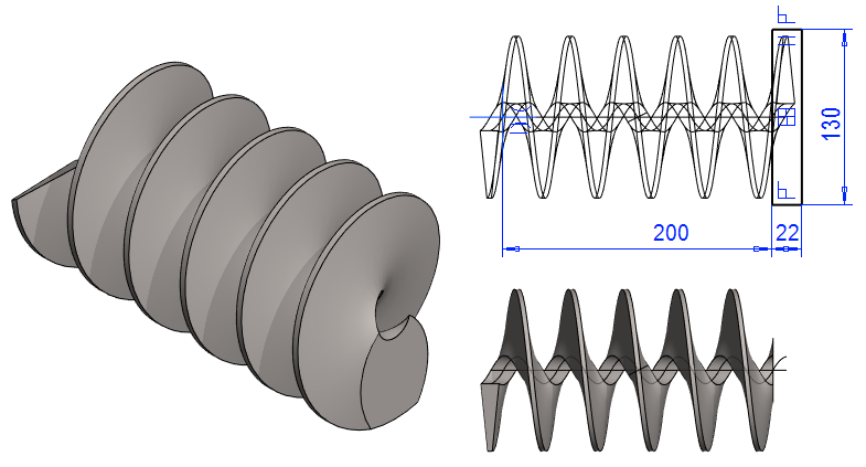
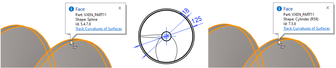
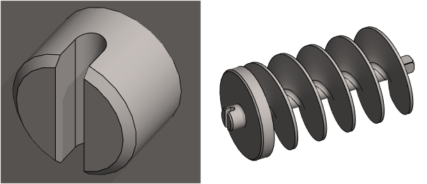
Create the outer surface of the screw to a cylindrical surface
As a result of the sweep, the surfaces of the screw are spline surfaces. In order for the Grinder Screw to go as closely as possible inside the cylinder, the model must be modified so that the outer surface becomes a cylinder surface.
-
New Sketch > To lateral (YZ) plane.
Sketch the shape
-
Sketch two circles with the center point at the origo.
-
Add diameter constraints.
-
Inner circle: 118.
-
The outer circle is slightly larger than the current outer circumference of the screw, e.g., 125.
-
-
Operation
-
Cutout > Extrude.
-
In Both Directions
-
Thru All
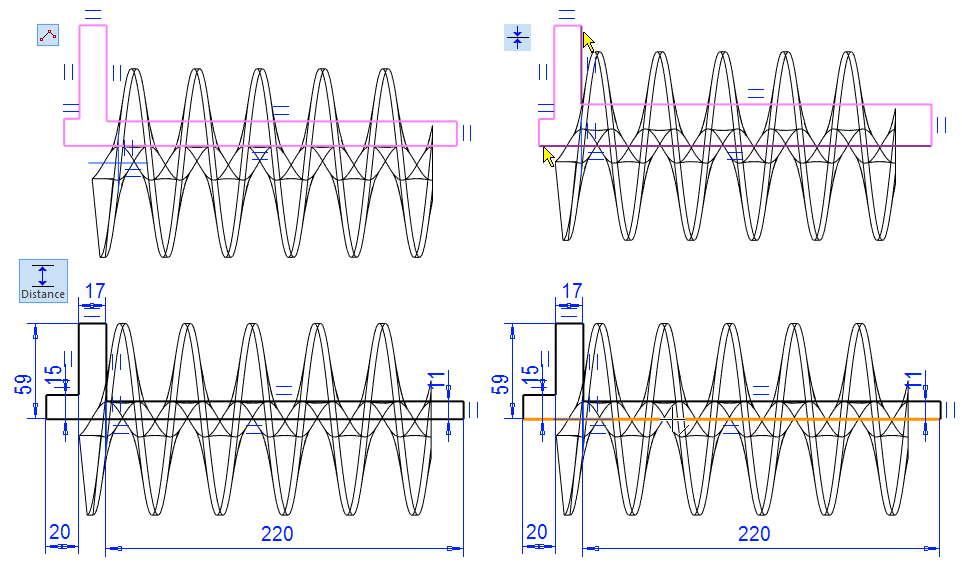
Model the body and shaft
-
New Sketch > To horizontal (XY) plane.
Sketch the shape
-
The function: Polyline (Line type: Shape)
-
Add a coincident constraint between the lower horizontal line and the horizontal line on the central cross.
-
Add a coincident constraint between the right vertical line and the vertical line on the central cross.
-
Dimension the sketch.
-
Operation
-
Boss > Revolve.
-
Angle: 360 (Default).
-
OK.
-
-
Click the rotation axis (Orange line in the lower right corner of the figure)
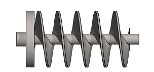
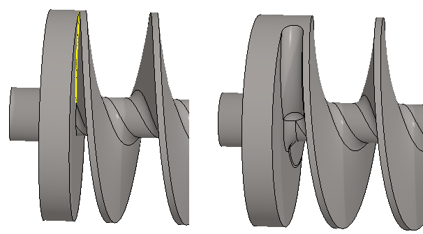
Create roundings at the junction of the screw threads and the shaft
-
Select both screw thread edges. (Remember

-
Right-click function: Add Round/Bevel > Round.
-
Value: 6.
-
Create a rounding at the junction of the screw thread and the rear frame
-
Select a sharp edge according to the figure.
-
Right-click function: Add Round/Bevel > Round.
-
Value: 6.
-
Create bevels at the ends of the shaft and frame
-
Click three lines. Yellow lines in the figure. (Remember
-
Right-click function: Add Round/Bevel > Single Edge Bevel.
-
Values: 2 and 2.
-
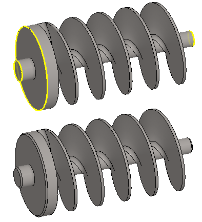
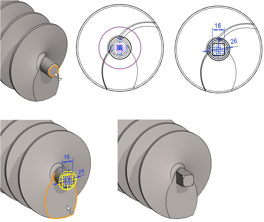
Shape the open end of shaft to rectangular.
-
Click the end face of the shaft.
-
Right-click function: New Sketch > Face.
Sketch the shape
-
Sketch a rectangle and a circle.
-
Add symmetry constraint to the rectangle in both directions with the central cross.
-
Enter the edge length: 16.
-
Add a diameter constraint to the circle.
-
Larger than shaft diameter or square diagonal, eg 26.
-
-
Operation
-
Cutout > Extrude.
-
To Selected Face. Click the face shown in the figure.
-
OK.
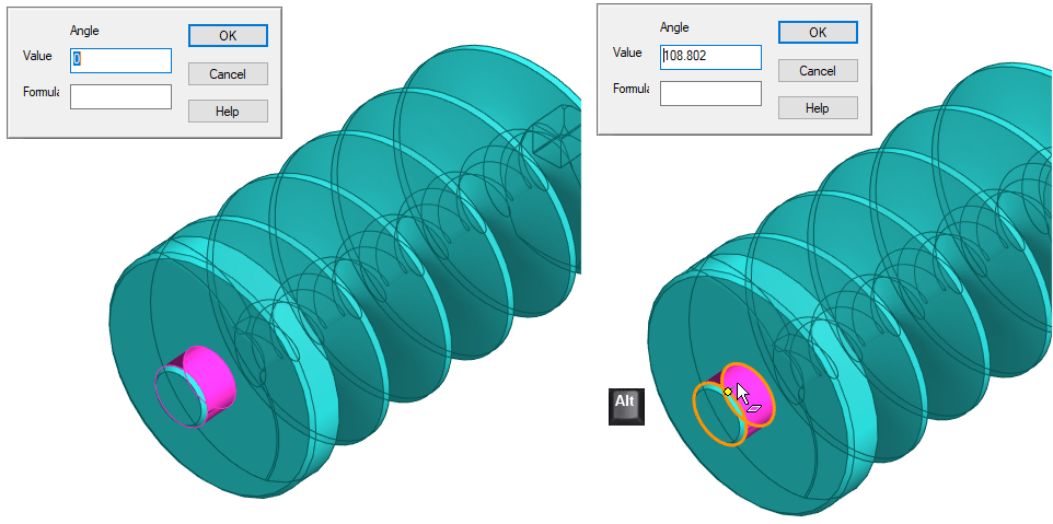
Create a slot at the other end of the shaft
-
Click the cylindrical surface shown in the figure.
-
Right-click function: New Sketch > Face.
-
The program suggests a value of 0 for the sketch direction.
-
-
Press and hold the Alt key and move the cursor over the cylindrical surface. You will notice that the value of the angle changes in the dialog in the upper left corner.
-
Enter the angle value: 90.
-
OK enters sketch mode.
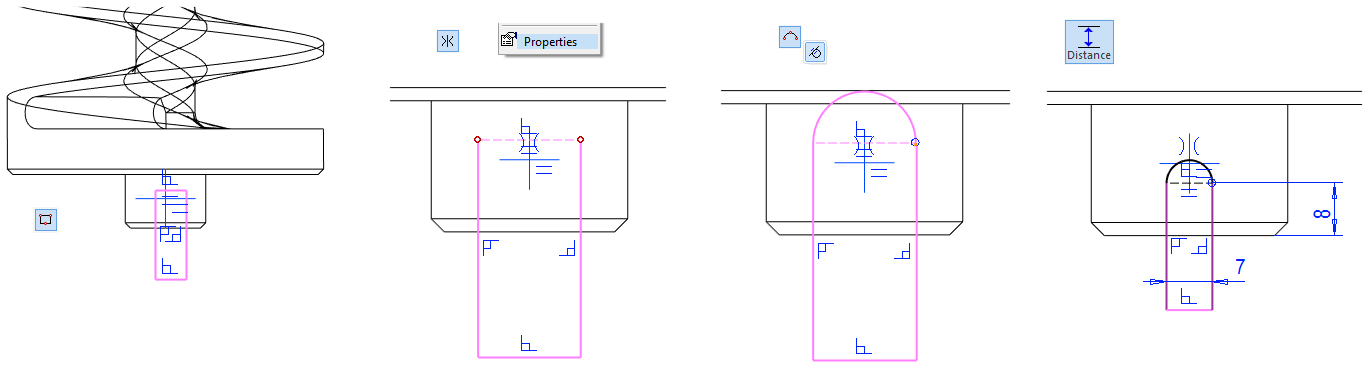
Sketch the shape
-
Rectangle.
-
Add a Symmetry constraint for the vertical lines with respect to the vertical line of the center cross.
-
Change the top horizontal line type to: Constr (Construction line).
-
Sketch an arc (Arc with tree point) tangentially to the vertical lines.
-
Dimension the sketch.
-
Operation
-
Cutout > Extrude.
-
Thru All
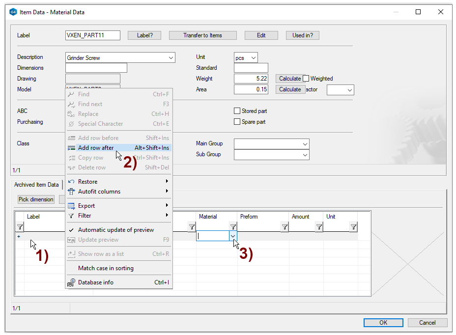
Enter item data of the part
-
Right-click function: Item Data.
-
Click on the line in the lower dialog, in the figure 1).
-
Right-click function: Add row after, in the figure 2).
-
Click the preselection button in the Material field, in the figure 3).
-
Select: Cast_Iron (by Double click).
-
Select: GRP600 (by Double click).
-
Also fill in part information (upper dialog), eg weight.
-
Press: Calculate.
-
-
OK.
Alternatively, you can enter information about the raw materia.
Create a drawing for the part
-
See Exercise 5 for more details.
Save the drawing
-
File > Save or click


Save the model
-
File > Save or click