

Exercise 10: Machining assembly
This exercise was carried out with version 27.0 (Vertex 2021).
In this exercise you will learn to
-
To make machinations in the assembly that are not visible in the parts of the assembly. Typically, such a situation is a structure welded from profiles, which is machined only after welding.
Functions to be used:
-
Importing a compressed model into a Vertex system.
-
Machining Features > Execute.
-
New Drawing for model.
-
Part numbering.
-
Properties of part > To Assembly Parts List.
Get a project that includes the necessary assembly
-
Download the Vertex project zip VXEN_PROF10.vxz here.
-
Drag the file from the downloads section of your Internet browser onto Vertex G4.
-
Be sure the models are found (in browser B) in project VX_COURSE_PROF.
-
If necessary, refresh your browser, if those models VXEN_PROF10* are not found immediately.
-
Open the assembly model
-
Press the

-
Select a project: VX_COURSE_PROF.
-
Open the model VXEN_PROF10.
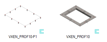
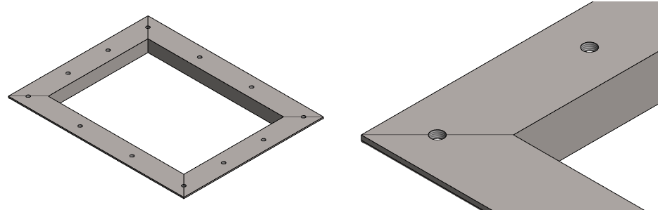
The model has a SKELETON part, which is used to add four L-profiles to the model, and a part (VXEN_PROF10-P1) with has only machining tools.


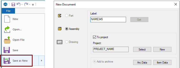
Save the model to your own project
-
Function: File > Save as New.
-
Enter the ID.
-
Fill in the archive information.
-
Select the project where the model will be saved or create a new project.
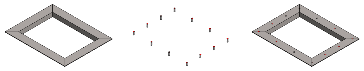
Perform machining
-
Right-click function: Machining Features > Execute.
-
Hide the part that contained the machining tool (The M key also drives the same thing).
This function is ideal in cases where machining cannot be carried out before welding, ie parts cannot be machined separately.
In cases where the parts need to be machined before welding, it is advisable to use the Boolean function and select the action from there: Subtract with tool.
-
For example, when a drawing is made for parts, which must show all machining.
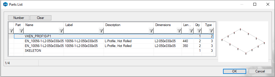
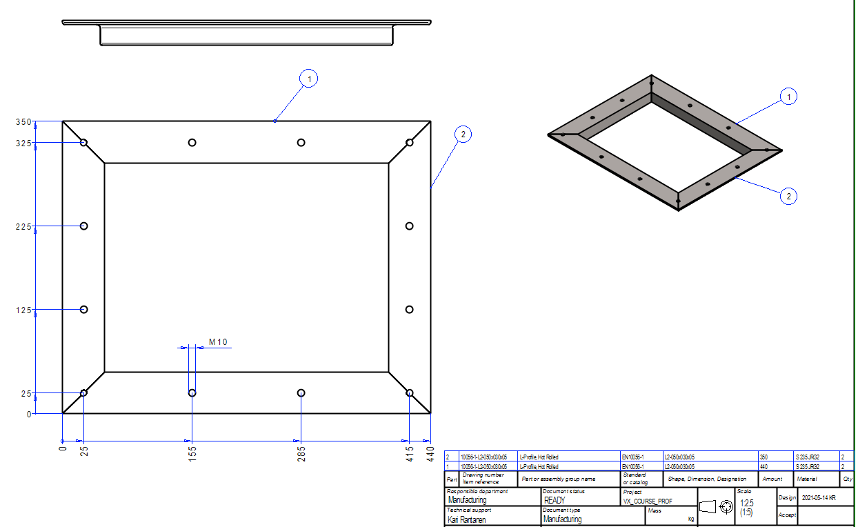
Create a drawing for the model
-
In the feature tree, click: Drawing.
-
Right-click function: New Drawing.
In the dialog New drawing, select data:
-
Scale: 1:2.5
-
Sheet: A3
-
Select projections: front and top.
-
Tangential lines: Draw as virtual shape lines (thin).
-
OK progresses to the archive data.
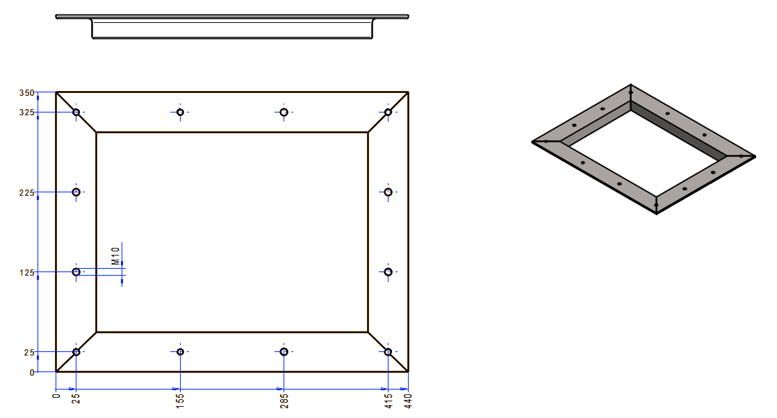
Add dimensions
-
Hole placement: (Dimensions group) Continuous baseline.
-
Hole diameter: Fast Dimensioning.
Add part numbers
-
Function: Parts List > Part number > Number.
Now you notice that both the machining tool (VXEN_PROF10-P1) and the SKELETON part are being added to the parts list.
-
Numbering should not be performed.
-
Press the Cancel.
-
Press the Cancel also in dialog Part Number.
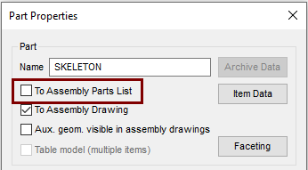
Remove the SKELETON part from the part numbering parts
-
Activate the model window. For example, with the Ctrl Tab key combination.
-
Click on the SKELETON part.
-
Right-click function: Properties.
-
Deselec: To Assembly Parts List.
Remove the Tool part from the part numbering parts
-
Click on the tool part (VXEN_PROF10-P1).
-
Right-click function: Edit.
-
Right-click function: Properties.
-
Deselec: To Assembly Parts List.
Exit from part to assembly
-
OK.
Add part numbers
-
Open or activate the drawing.
-
Function: Parts List > Part number > Number.
-
Press Number.
-
OK (in Parts List dialog).
-
OK (in Parts Number dialog.
-
Click the highlighted part.
-
Click the location of the part number symbol.
-
Finish numbering the parts with a Done acknowledgment when both parts are numbered.
-


-
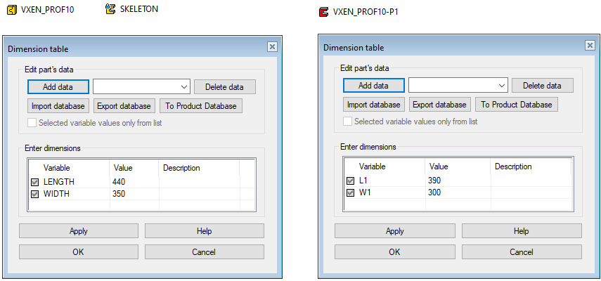
You can vary the models as needed
-
Both models have dimension variables.
-
You can vary the profiles directly in the assembly model because the dimension variables of the local part (SKELETON) are presented in it.
-
You can vary the part that contains the tools by editing the part model (VXEN_PROF10-P1).
Save the drawing
-
File > Save or click


Save the model
-
File > Save or click