Exercise 10: Explosion functionality
This exercise was carried out with version 28.0 (Vertex 2022).
In this exercise you will learn to
-
To move the part and subassembly to the explode station.
-
Animate transitions of part's explode stations
-
To combine separate explode transition to occur simultaneously.
-
To modify the order of explode transitions.
-
To Remone explode transition.
-
To define the projection of a drawing to describe explode stations.
Functions to be used:
-
Assembly: Explode
-
Drawings > New
-
Properties (of drawing's projection)
-
Feature tree of assembly: Tree > Tree data.
Get a project that includes the necessary parts and assemblies
-
Download the zipped Vertex project (VX_AS10B.vxz) here.
-
Drag the file from the downloads section of your Internet browser onto Vertex G4.
-
Be sure the models are found (in browser B) in project VX_COURSE_ASSY.
-
If necessary, refresh your browser, if those models VX_AS910-* are not found immediately.
-
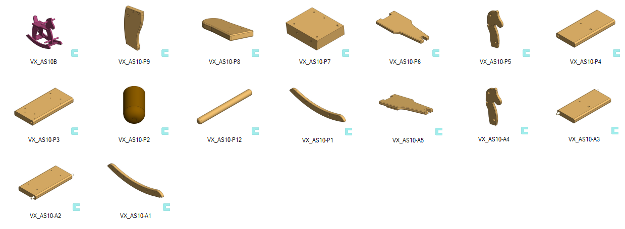
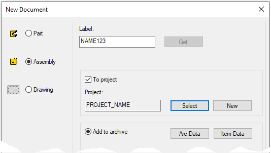
Read the assembly and save it as a new one
-
File > Open: VX_AS_10B. (Rocking horse).
-
File > Save as New (> Save as New).
-
Enter the ID and Archive data and create a new project or select the old one.
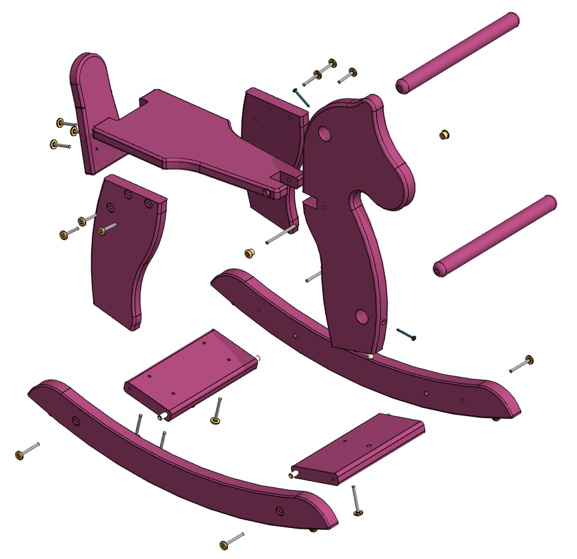
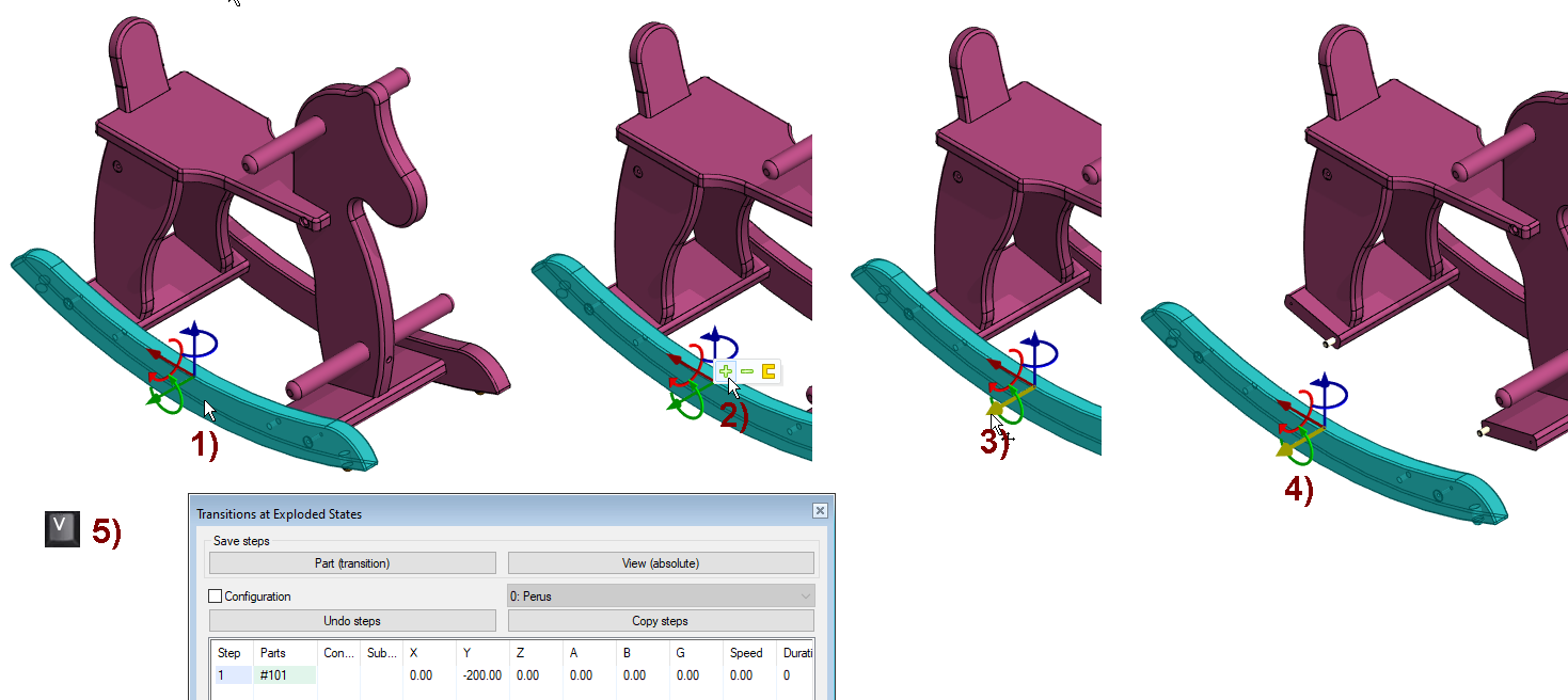
Explode the first stand
Stands of rocking horse are assemblies, so they must be chosen as an assembly.
-
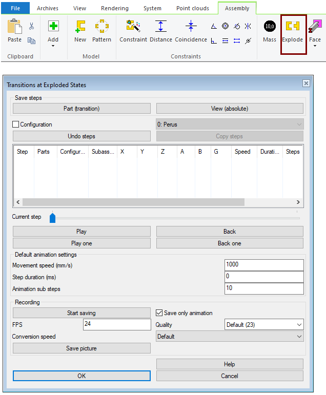
Function: Explode.
-
The dialog Transitions at Explodes States is opened.
-
-
Click to one stand. In the figure 1).
-
Move the cursor slightly to the right diagonally to open the Mini Toolbar.
-
Click the

-
Click to the arrow on the handle in which you are moving or rotating the part. Here it is the green arrow. In the figure 3).
-
Drag it in the desired direction.
-
Point to a place. In the figure 4) or enter the transiotion's length.
-
Save the transitions with a Done acknowledgment. In the figure 5). wherein the selected part, parts or subassembly and offsets are stored in a table.
-
V key or
-
The middle button of mouse or
-
Right-click function: OK
-
You can make to multiple transitions in the model and then acknowledge the transitions done, at which point each transition you make is added to the table as a separate row.
If you didn’t notice the choice of assembly, then only one part transferred and the pieces limiting the swinging remained in place.
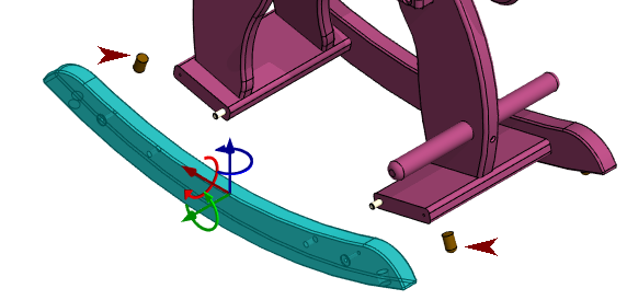
If you forgot to select the assembly with the Plus sign immediately after clicking to a part, then it is wise to press the Esc key and select the part again, because the Mini Toolbar will only appear, if you move the cursor to the top right immediately after the click.
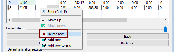
If you moved the part into place and added the transition to the transiotion table, then the simplest way is to delete the row and move the assembly again.
-
Hover over the line.
-
Right-click function: Delere row.
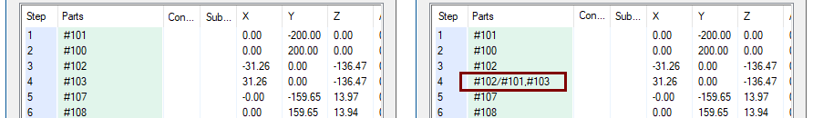
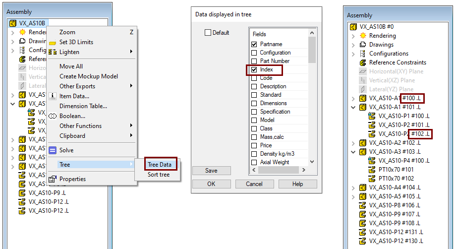
It is possible to add a part or sub assembly to a row in the transition table. To do this, you need to know the instance ID of the part or subassembly. You can find out the index in the feature tree with the function: Tree > Tree information. Deselect Default and include Index.
-
Each part or subassembly receives a sequential index number when it is added to the assembly. The index of the first part is #100, the second #101, the third #102, etc.
-
In this case, for example, the index of the second part of the third subassembly added is #102/#101.
In the Parts field, enter the index of the part or subassembly, separated by commas.
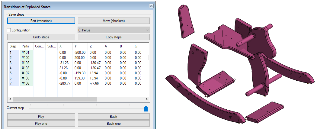
Explode the second stand
-
Click to second stand.
-
Move the cursor slightly to the right diagonally to open the Mini Toolbar.
-
Click the
-
Click to the arrow on the handle in which you are moving or rotating the part. Here it is the green arrow.
-
Drag it in the desired direction.
-
Point to a place
or enter the transiotion's length.
-
Save the transitions with a Done acknowledgment.
-
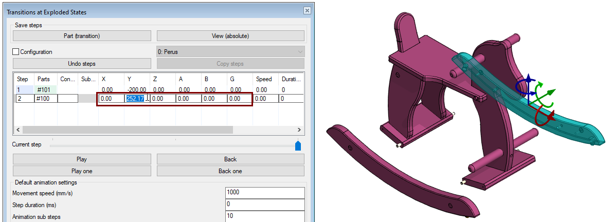
In the table, click the row that describes the transition.
-
Click the field whose values you want to change.
-
Change the values for the offset or rotation.
-
Note the signs. The plus sign indicates a move in the direction of the arrow and the minus sign indicates the opposite direction.
-
The rotation only accepts positive values.
-
The explode positioning is recalculated, for example, when you use the cursor on top of the graphics window or click on another field in the table.
-
-
Fields X, Y, and Z contain offsets in the direction of the part's own X (red), Y (green), or Z (blue) axis.
-
Field A (Alpha angle) contains the rotation about the X axis, i.e. the red axis. (translation according to the "right hand rule").
-
Field B (Beta angle) contains the rotation around the Y-axis, i.e. the green axis.
-
Field G (Gamma angle) contains the rotation about the Z axis, i.e. the blue axis.
Test the movements of transitions table
-
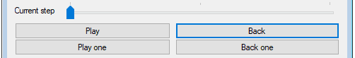
Click the Back.
-
Both stands in turn slide into place.
-
-
Click the Play.
-
Both stands slide in turn to the explode stations.
-
-
Click the Back one.
-
Only the second stands slides into place.
-
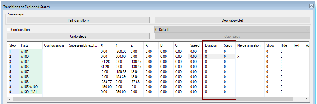
Combine the transitions
-
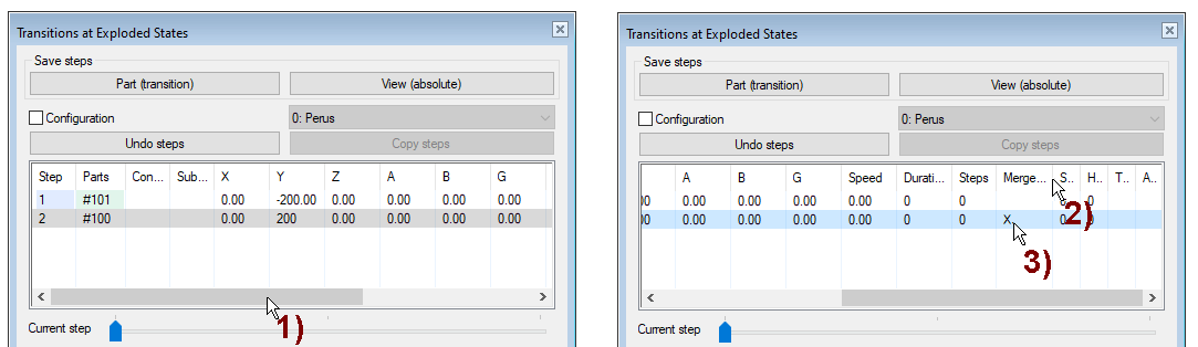
Slide more columns to appear in the Transition at Exploded States dialog. In the figure 1).
-
You can see the name of the columns that appear in one letter if you drag the column wider. In the figure 2).
-
You will see that the M .. column name is Merge Animation.
-
-
Click the Merge ... field in the latter row to mark the field with an x. In the figure 3).
-
Click the Back and Play buttons alternately.
-
You will see that the stands slide at the same time.
-
Leave the stands in the exploded position before proceeding to give another transions.
-
The new transition follows its previous repeated transition.
-
If you want the new transition to be the first transition, then drive the transitions Back first.
Move both supports (as assemblies) down
Note that the supports are assemblies wiht plate and two round pins
-
Click (rear) support.
-
Select the Plus button in the Mini Toolbar so that the round pins are also selected.
-
Click the blue axis.
-
Drag the assembly down.
-
Enter the transition 140.
-
Click (front) support.
-
Select the Plus button in the Mini Toolbar so that the round pins are also selected.
-
Click the blue axis.
-
Drag the assembly down.
-
Enter the transition 140.
-
Save the transitions with a Done acknowledgment.
-
You will see that both transitions are added to the table on their own rows.
-
Note that although you moved the supports in the directions of the blue axis 140mm, the transitions in the transitions table are recorded in the direction of the coordinate system of assembly.
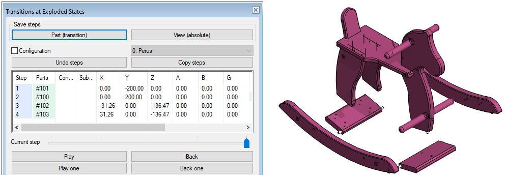
Move the hind legs to the sides
-
Click to the (right) foot.
-
Click the blue axis.
-
Drag the assembly outward.
-
Enter the transition 160.
-
Click to the (left) foot.
-
Click the blue axis.
-
Drag the assembly outward.
-
Enter the transition 160.
-
Save the transitions with a Done acknowledgment.
Move the tail back
-
Click to the tail.
-
Click the blue axis.
-
Drag the tail backwards.
-
Enter the transition 300.
-
Save the transitions with a Done acknowledgment.
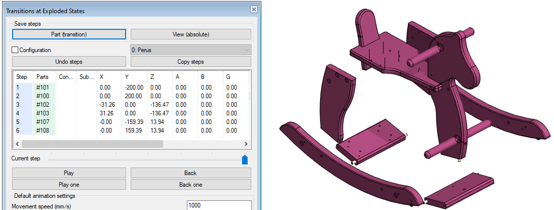
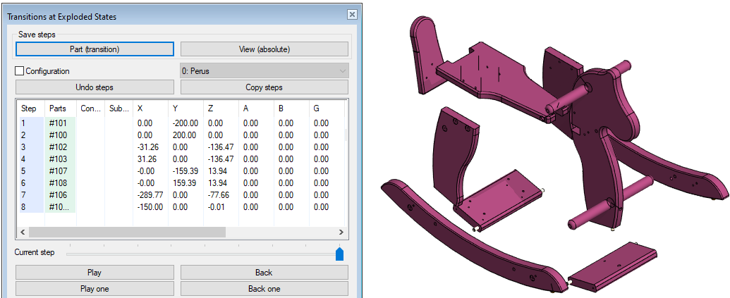
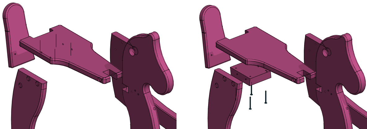
Move the back (saddle) backwards
Note that the back (saddle) is assembly of two-parts and four screws.
-
Click to the back.
-
Select the Plus button in the Mini Toolbar so that the all parts of that assembly are also selected.
-
Click the red axis.
-
Drag the assembly backwards.
-
Enter the transition 150.
-
Save the transitions with a Done acknowledgment.
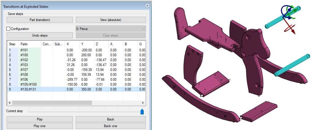
Move the round bars to the side
-
Click both round bars (Remember the Ctrl key).
-
Click the green axis.
-
Drag the bars to the right.
-
Enter the transition 350.
-
Save the transitions with a Done acknowledgment.
Save the transiotions of Exploded States
-
Click the OK button in the Transition at Exploded States dialog.
-
Save the model.
Repeat the Explode
-
Function: Explode.
-
The parts move to the previously defined explodes stations and
-
The dialog Transitions at Explodes States is opened.
-
-
If necessary, you can change the size of the transitions
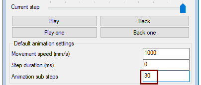
Adjust the number of steps in the animation
The three values below in the Animation Defaults affect all stages of the animation, unless they have individual values.
-
Change the number of sub steps in the animation.
-
Default is 10.
-
-
Change the number of sub steps to 30.
-
Use the Play and Back buttons to test the movement.
-
You can see that the movement happens in smaller jumps, i.e. the movement is smoother.
-
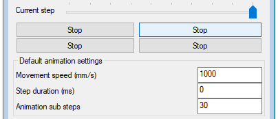
Stop motion during animation
When the animation sequence is in progress, all the Play and Back buttons will be replaced by the Stop button.
-
Click one of the Stop buttons to stop the movement.
The animation continues when you click any of the Play and Back buttons.
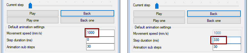
Adjust the animation speed and / or step duration
-
You can adjust the movement speed either by entering the movement speed (mm/s) or by entering the step duration (ms).
Adjust the duration of a single step or the number of steps
-
Click the row whose settings you want to adjust.
-
Enter the duration of the movement (in milliseconds) and the number of steps, if different from the default Animation Sub-Steps setting.
Hide or restore the visibility of the part at the end of the movement
-
Click the row whose part or subassembly you want to hide or restore.
-
Enter the duration of the hide (in milliseconds) in the Hide column.
-
Enter the recovery time (in milliseconds) in the Show column.
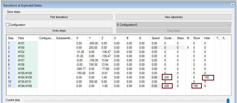
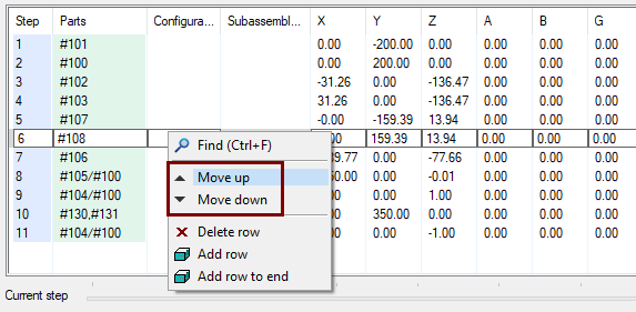
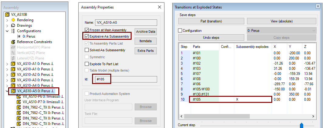
In the figure on the right, the head of a rocking horse (first part #100 of assembly #104 ) has been selected, which has been moved 1 mm (without movement, no hiding or restoration ). The duration of the movement is 200 ms and the hiding and recovery time is 190 ms.
-
The head is selected to be hidden in step 9.
-
After step 10, a row is added to the list with the right-click function Add row to End.
-
The head address (#104/#100) is copied to the line and has the head visibility restored.
The Show and Hide fields enter the change in visibility in milliseconds.
-
Hiding without movement is not possible.
-
Note that the Hide and Show change time must be as long or faster than the step duration for the change to take place completely.
Change the execution order of the animation.
-
Click the row whose execution order you want to change.
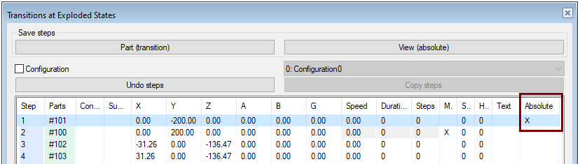
Determine the explode states in absolute coordinates
By default, the program saves the transitions, but if the Absolute column is selected, the program interprets the transitions and rotations according to the absolute coordinate system of the assembly.
The text added to the Text column appears in the Vertex message bar (bottom left).
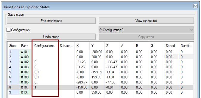
Configuratios have various explode station. Making a stacking instruction
If you want to make several different explode stations on the same assemblyl, eg to present phased explode images (Stacking instructions), you can do this by making the required number of configurations in the model and multiplying it the explode station is affected.
-
An empty column means that the explode affects all configuratios.
See the explosion of a configuration.
-
Activate a configuration first.
-
Then perform the Explode function.
In the same drawing you can add the projection of every configurations. Define each projection to describe an exploded image to get a phased stacking guide.
Explosive as a subassembly
-
In order for a subassembly to explode, it must be in the main assembly to give it the property Subassembly Explosive.
-
After this, the subassembly also explodes in the main assembly.
Note: Explode stations are not defined in the example model for the saddle assembly (VX_AS10-A5).
-
If you want to try it out, first define the subassembly explode stations, save the model, and update it to the main assembly.
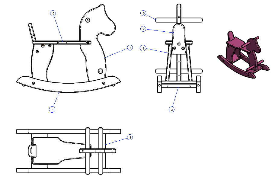
Create a drawing for the model
For more detailed instructions, see the Modeling parts course exercise 5 Drawing of Model.
-
Select also an isometric projection.
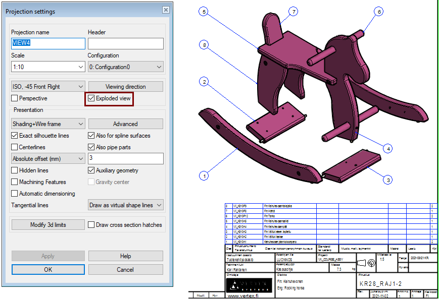
Define the isometric projection as an exploded view
-
Double-click to the ispometric projection or
-
Select the projection and the right-click function: Properties.
-
-
Select the setting: Exploded view.
Save the model
-
File > Save or click


-
Explode stations are defined in the model, but they are made differently than described in this exercise.