

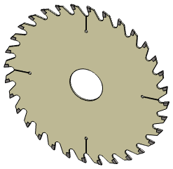
Exercise 10: Circular saw blade
This exercise was carried out with version 27.0 (Vertex 2021).
In this exercise you will learn to
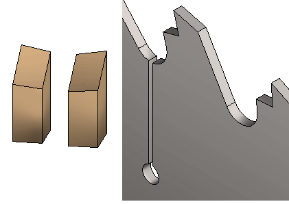
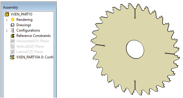
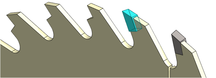
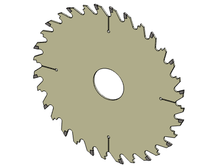
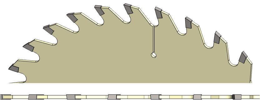
A 32-tooth blade circular saw blade with a frame and separate carbide blades (an assembly) is modeled. Every other tooth is right-handed and every other tooth is left-handed.
-
Add a series of polar features and polar parts.
-
Simple assembly creation.
-
Creating a pattern of part using the feature pattern from the part.
Functions to be used:
-
We review sketching tools.
-
Pattern (Polar).
-
Draft.
-
Configuration > Add Configuratio, Configuration > Properties > Nam.
-
Mirror.
-
Add > Model
-
Assembly constraints: Coincident and Distance.
-
Assembly: Pattern.
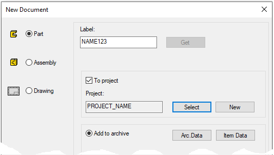
Create a new part
-
File > New > Part.
-
Enter the label (which is also the name of the model and by default will be the name of the drawing).
-
Enter the archive information by clicking Arc.Data.
-
Select the project for model.
-
OK.
-
Model the circular saw blade body
-
New Sketch > To vertical (XZ) plane.
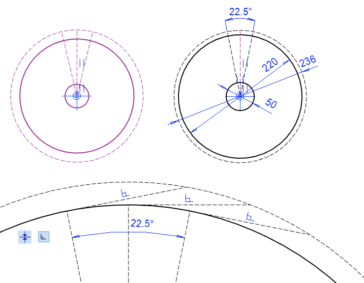
Sketch the shape
-
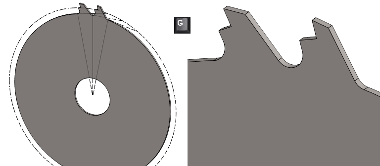
Sketch three circles, diameters 50, 220 and 236 (outermost with the line style: Guide).
-
Sketch a vertical line (type: Guide line) ending in a medium-sized circle (= endpoint coincident with it).
-
Sketch oblique lines (type Guide line) ending in a medium-sized circle (= endpoint coincident with it).
-
Add a symmetry constraints for oblique guide lines with respect to the vertical line.
-
Add an angle constraints of 22.5° between the oblique guide lines.
-
At the end of each guide line, sketch a section line of the guide line and add a perpendicular constraint with the line on the line. (see adjacent bottom figure)
-
These guide lines are used when sketching tooth frames.
-

Operation
-
Boss > Extrude.
-
In Both Directions
-
Lenght: 2.
The 22.5 ° degree comes from modeling two teeth at once in this exercise.
Model a pair of teeth
-
New Sketch > To vertical (XZ) plane.
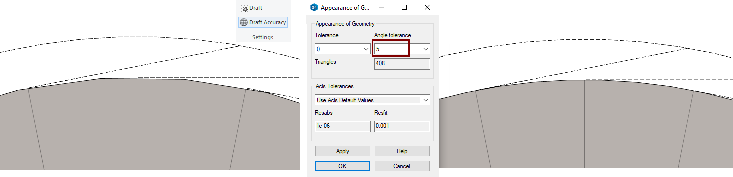
If the model looks angular, adjust the setting Draft Accuracy.
-
You can find it on the View tab, in the Settings group
-
Angle tolerance: 5.
You can only adjust this value if you are not in skecth mode.
Sketch the shape
-
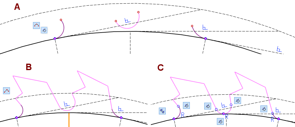
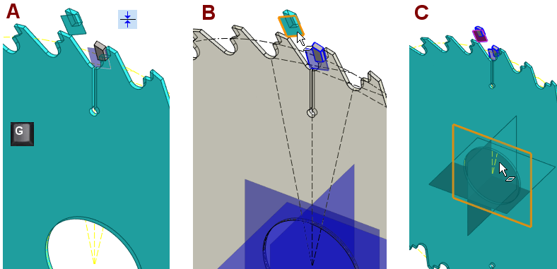
Sketch three arcs, in the figure A.
-
The outermost arcs begin to tangentially from the ends of the guide lines.
-
-
Sketch a polylines, in the figure B.
-
The line starting from the arc coincides with the guide line.
-
-
Add Equal Radius constraint for all three arcs, in the figure C.
-
Add Tangential constraint between lines and arcs, and between the center arc and the guide geometry, in the figure C.
-
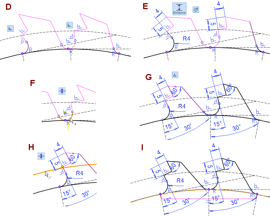
Add Perpendicular constraints, in the figure D.
-
Add Distance constraints, in the figure E.
-
Click on the lines when you add the distance constraint 4.
-
-
Add Radius constraints, in the figure E.
-
Add Coincident constraint between the center of the arc and the vertical guide line, in the figure F.
-
Add Angle constraints, in the figure G.
-
If the sketch is not fully defined, then add the necessary Coincident constraint, in the figure H.
-
Close the shape, sketching the polyline, in the figure I.
-
Without this line, you cannot extrude.
-
-
Operation
-
Boss > Extrude.
-
In Both Directions
-
Lenght: 2.
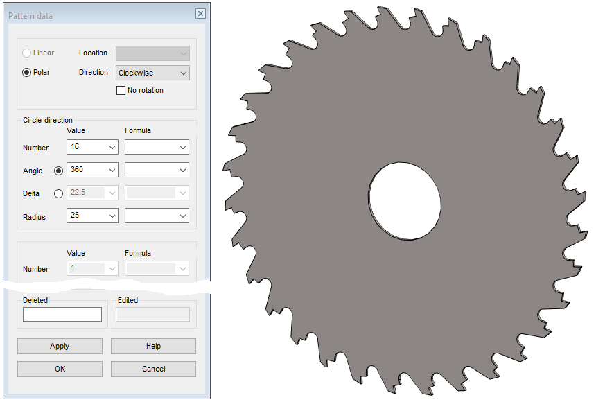
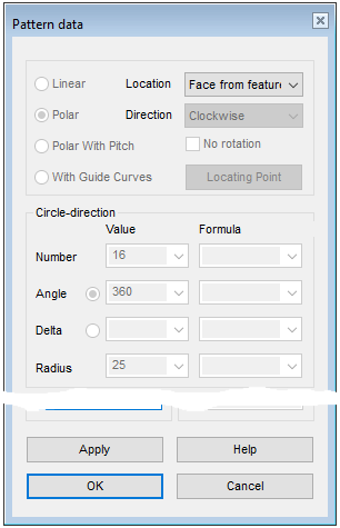
Create a pattern of teeth
-
Select the last feature from the feature tree.
-
Right-click function: Feature pattern.
-
Polar.
-
Circle/direction, Number: 16.
-
Angle: 360 (= Default).
-
Radius: 25. (This does not matter much. The program draws a guide line of the given radius on the model).
-
-
OK.
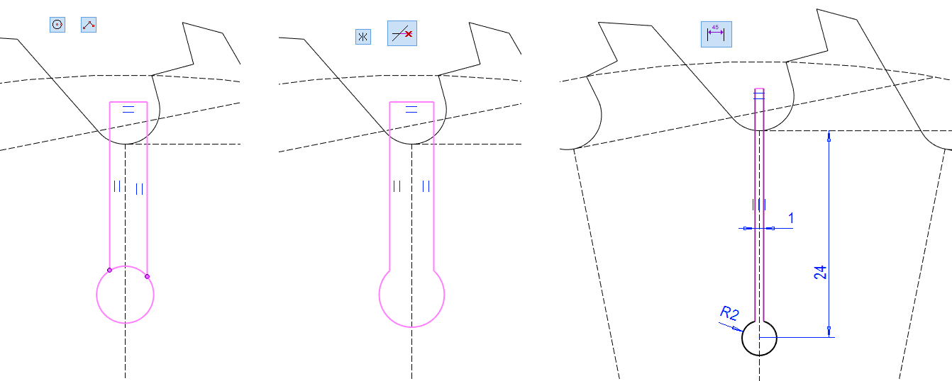
Model the thermal expansion groove
-
New Sketch > To vertical (XZ) plane.
Sketch the shape
-
Sketch a circle and a polyline.
-
The ends of the polyline coincide with the circle.
-
-
Add Symmetry constraint between the vertical lines and the guide line.
-
Use the Delete section of Line to remove a piece from the circle.
-
Add Dimension constraints.
-
Groove width: 1.
-
Radius: 2.
-
Distance: 24.
-
-
Operation
-
Cutout > Extrude.
-
In Both Directions
-
Thru All
Create a polar pattern from the thermal expansion groove
-
Select the last feature from the feature tree.
-
Right-click function: Feature pattern.
-
Polar.
-
Circle/direction, Number: 4.
-
Angle: 360 (= Default).
-
Radius: 25. (This does not matter much. The program draws a guide line of the given radius on the model).
-
-
OK.
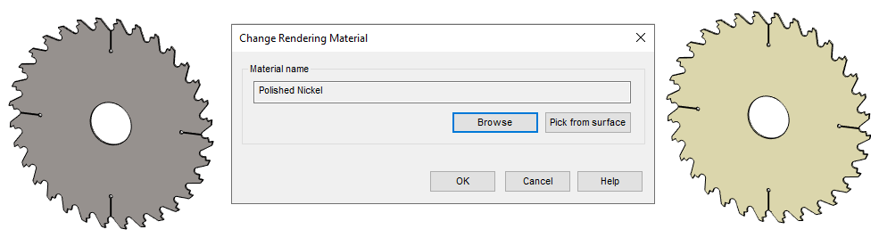
Give visualization material for the frame
-
Right-click function: Rendering > Change Material.
-
Browse
-
Search the library for visualization material: Metals > Steel > Polished Nickel.
-
OK.
-
Save the blade body
-
File > Save or click


Create a new part (carbide tooth)
-
File > New > Part.
-
Enter the label (which is also the name of the model and by default will be the name of the drawing).
-
Enter the archive information by clicking Arc.Data.
-
Select the project for the model.
-
OK.
-
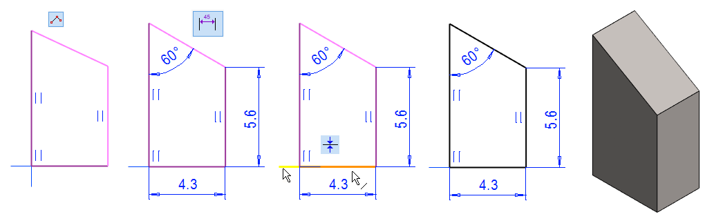
Create the feature
-
New Sketch > To vertical (XZ) plane.
Sketch the shape
-
The function: Polyline.
-
Add the Dimension constraints, shown in the figure.
-
Add the Coincident constraints, shown in the figure.
-
Operation
-
Boss > Extrude.
-
In Both Directions
-
Lenght: 2.8.
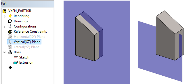
Resize the auxiliary plane
-
Restore plane Vertical(XZ) Plane if it is hidden.
-
Select Vertical(XZ) Plane.
-
Right-click function: Change Size.
-
Enter the new size: 10.
Create the draft to the tooth (So that the blade cuts well)
-
Click the two faces to be drafted.
-
Right-click function: Draft.
-
Click a reference face (whose dimensions do not change)
-
In the Dialogue Draft.
-
Angle: 5.
-
Remove.
-
-
OK.
The dimensions of the part remain at the clicked reference level.
-
Remove = Remove the geometry from the reference level.
-
Add = Add the geometry from the reference level.
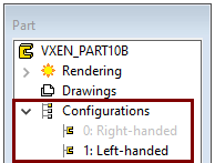
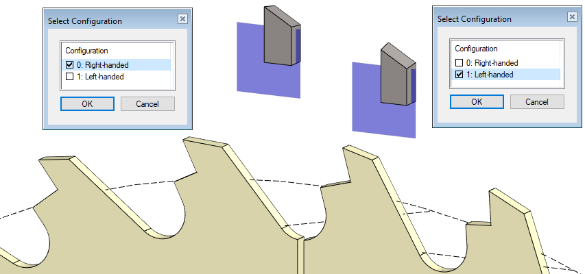
Add a new configuration and give name
-
Add a new configuration.
-
Click Configurations.
-
Right-click function: Add Configuration.
-
-
Name the configurations.
-
Click the Configuration in the feature tree.
-
Right-click function: Properties.
-
Enter the name of the configuration in the menu that opens: Left-handed and other Right-handed.
-
OK.
-
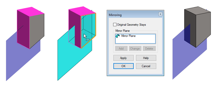
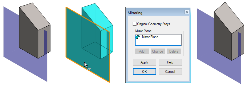
Mirror the part
-
The function: Mirror (Mirror the whole geometry of the part).
-
Click to the face that acts as the mirror plane.
-
Deselect the dialog: Original Geometrt Stays.
-
OK.
Save the tooth
-
File > Save or click
Create a new assembly
-
File > New > Assembly.
-
Enter the label (which is also the name of the model and by default will be the name of the drawing).
-
Enter the archive information by clicking Arc.Data.
-
Select the project for the model.
-
OK.
-
Add the blade body
-
Right-click function: Add > Model.
-
Find the model, for example, in the History > Recent branch (or under the right project).
-
Double-click the part.
-
Place this first part to the origo of the assembly
-
Instead of an indication, press the "Done" button (= V key of middle mouse button or Right-click function: OK.)
-
-
Use the Esc key to abort the addition of parts
-
If you press the V key or select the Right-click function OK, the program interrupts the addition of the selected part and asks you to select the next part to be added.
-
The program locks the first part in place by default, so you can't drag it.
The Add > Model function described above opens the so-called a model addition browser whose functions are trimmed to add parts to the assembly.
If you are using a universal browser that opens with the B key, click the part and drag it a short distance and release the mouse selection button to add the part to the assembly.
-
Double-clicking in the universal browser (B) does not add the part, instead it opens the model in separate window.
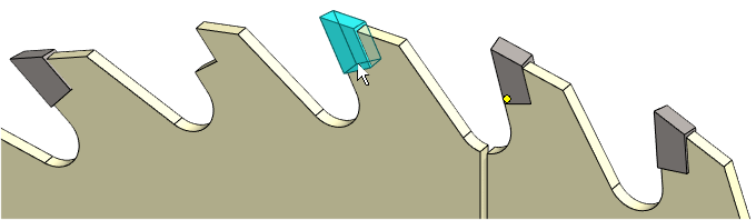
Add two teeth to the assembly
-
Right-click function: Add > Model.
-
Find the model, for example, in the History > Recent branch.
-
Click the tooth part and drag it a short distance and release the mouse selection button.
-
The program asks you to select a configuration.
-
Select the first configuration.
-
-
Select the location of the tooth.
-
V key return to select a new model
-
-
Click the tooth part and drag it a short distance and release the mouse selection button.
-
The program asks you to select a configuration
-
Select the second configuration.
-
-
Select the location of the tooth.
-
Esc (Stop adding parts).
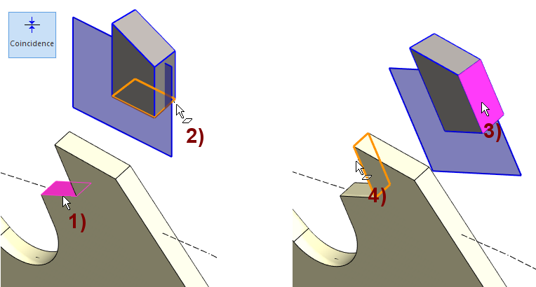
Position the parts
-
Function: Coincidence (in the Ribbon).
-
Click the face of the body and face of tooth you want to add the considency.
-
Order 1) and 2) then 3) and 4).
-
Note that you can select the face behind the edge if the cursor is slightly outside the edge and there are no other faces under the cursor.
-
-
Add a constraints for both teeth.
-
OK: stop adding constraints.
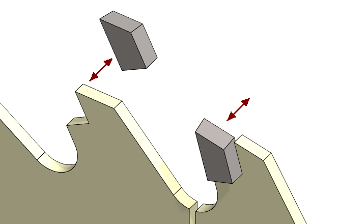
Drag teeth
-
Click the tooth and hold down the mouse select button and drag the tooth.
-
The tooth slides according to constraints (as if it were moving on rails).
Place the centerline of the tooth on the centerline of the body
We can take advantage of the coincidency constraint and auxiliary levels because we extruded both the body and the tooth In both directions.
-
If we had not done so, then our teeth would have to be placed with a distance constraints.
Put the parts in place:
-
Restore the auxiliary geometry if it is hidden (G key).
-
First select body and tooth (Remember Ctrl key)
-
Right-click function: Constraints > Coinsidence.
-
The program stains the first part with attention color.
-
-
Click the auxiliary plane.
-
The program stains the second part with attention color.
-
-
Click the auxiliary plane.
-
The program announces: Assembly is fully defined!
-
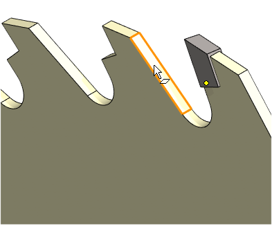
Make a pattern of the first tooth
In this exercise, a teeth pattern is added to using the features pattern of the body.
-
Click to the first tooth, either from the model or feature tree.
-
Right-click function: Pattern.
-
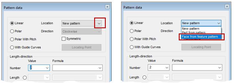
In the Pattern Data dialog, change the location of the pattern: From New pattern to Fase from feature pattern.
-
Click on a face of feature.
-
The program deactivates the dialog fields (except for the Deleted field).
-
-
OK completes the pattern.
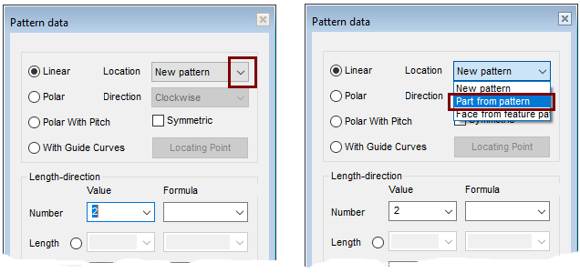
Make a pattern of the secont tooth
-
You can do the pattern in exactly the same way as above.
-
Or you can use a part in a pattern to create a new, similar pattern.
-
In the Pattern Data dialog, change the location of the pattern: From New pattern to Part from pattern.
-
Save the model
-
File > Save or click
Download the circular saw blade assembly model (VX_PART10.vxz) here
-
The file also contains sub-models: Blade frame VX_PART10A and tooth VX_PART10B.