

Exercise 1: Frame, miter trimmed
This exercise was carried out with version 27.0 (Vertex 2021).
In this exercise you will learn to
-
Use of the control curve part (skeleton / jig) in modeling profile structures.
-
Add a profile to the control curve with automatic miter trimming selected.
-
Creating a drawing.
-
Generation of a profile list (cutting list) to a text file.
-
Generating a profile list (cutting list) in Excel.
-
Generation of a profile list (cutting list) to a new Drawing.
-
By modifying the control curve part to change the dimensions of the profiles.
Functions to be used:
-
New local part of the assembly.
-
Sketching: Two-point rectangle and dimensioning.
-
Add > Profile
-
Drawing > New
-
Parts list
-
Editing a part in an assembly.
-
Editing a sketch.
-
Solve (profiles after editing the guide curve geometry).
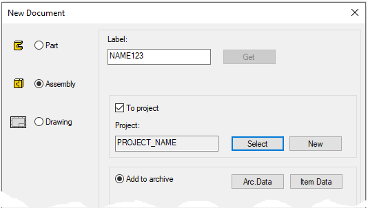
Create a new assembly
-
File > New > Assembly.
-
Enter the label (which is also the name of the model and by default will be the name of the drawing).
-
Enter the archive information by clicking Arc.Data.
-
Select the project where the model will be saved.
-
OK.
-
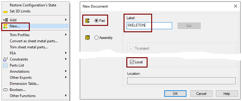
Create a new local part (Skeleton - Guide curve)
-
Right-click function: New > Part
-
Enter a name, eg SKELETON or JIG.
-
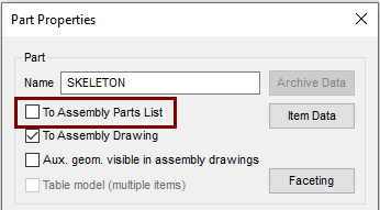
Define that the control curve part does not appear in the parts list
-
Right-click function: Properties
-
Deselect the settings: To Assembly Parts list, because this part is not desired in the parts list, after all it is a completely "intangible" part.
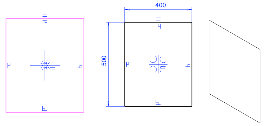
Sketch the skeleton (control curve)
-
Right-click function: New Sketch > To vertical (XZ) plane.
-
Sketch a rectangle and add dimensions; 500 and 400.
Operation
-
Guode Curve.
If the guide curve is not visible, then it is because the auxiliary geometry is hidden.
-
Use the

Exit from part to assembly
-
OK.
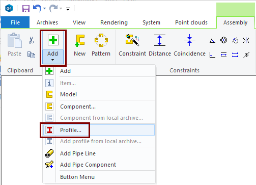
Add profiles
-
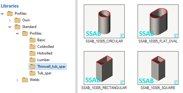
Right-click function: Add > Profile.
-
Select the profile from the library Profiles > Thinwall_tub_spar > SSAB_10305_SQUARE.
-
Select size: SSAB_50x2.
-
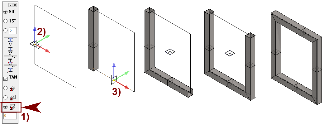
Select the trimming mode: Trim automatically to edge, in the figure 1).
-
Click on the guide curve line, in the figure 2).
-
Click on the second line of the guide curve, in the figure 3).
-
Click the third and fourth lines.
-
Stop adding profiles with the

Use the Add > Profile on the ribbon.
If you already have profiles in your assembly and want to add a similar profile (of the same type and size), then:
-
Click on the profile.
-
Right-click function: Add > Same profile.
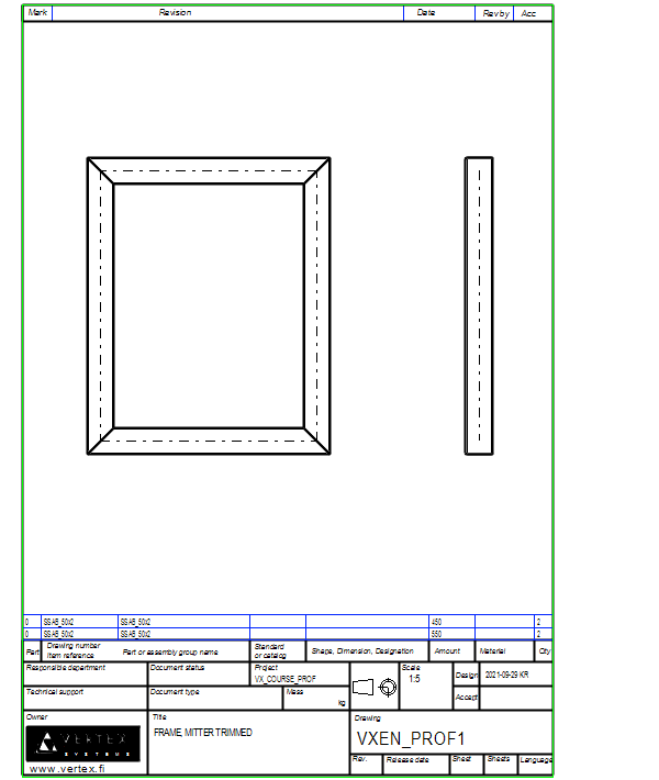
Create a drawing for the assembly
-
In the feature tree, click Drawings.
-
Right-click function: New Drawing.
-
Scale: 1:5
-
Sheet: A3
-
Select projections: front, top and left.
-
Tangential lines: Draw as virtual shape lines (thin).
-
OK progresses to the archive data.
-
For more detailed instructions, see the Modeling parts course exercise 5 Drawing of Model.
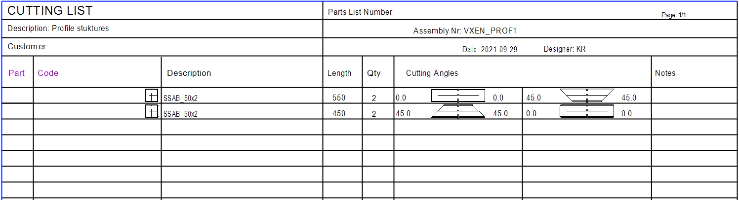
A list of parts is printed on the drawing, which includes the profile lengths in the Amount field.

Save the drawing
-
File > Save or click


-
Remember that the model must be saved once after creating the drawing so that the drawing ID is stored in the model's feature tree, under Drawings, through which you can later read the drawing.
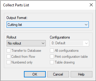
Print the cutting list to a text file
To print a cutting list from the profiles in the assembly to a text file, follow these steps:
-
Right-click function: Parts list.
-
Select the Output format: Cutting List.
-
Enter the file a name and select a directory.
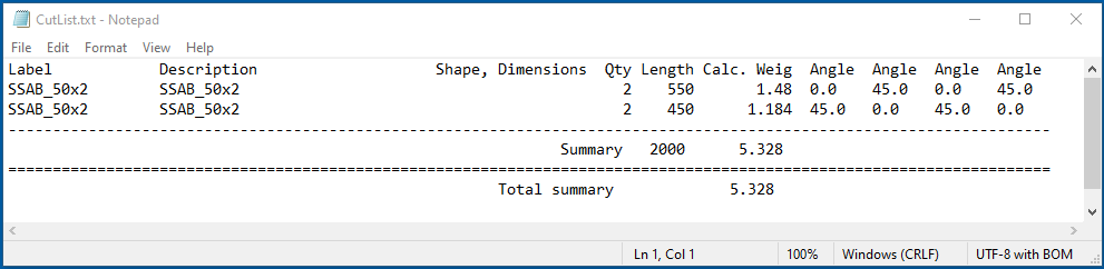
This list also shows the cutting angles.
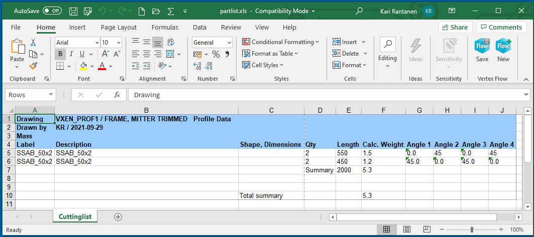
Print the cutting list to Excel
-
Right-click function: Parts list.
-
Select the Output format: Cutting List to Excel.
-
Depending on the Excel settings:
-
Excel opens and a cutting list is generated there.
-
Excel opens, but Excel asks permission to run macros.
-
Excel doesn't even open because macros are disabled.
-
-
Enter the file a name and select a directory.

If the list is not generated in Excel, you must allow Excel macros to run
-
Either always.
-
Or, when prompted to run macros, allow it.
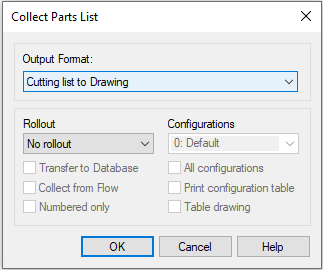
Print a cutting list to Drawing.
-
Right-click function: Parts list.
-
Select the Output format: Cutting List to Drawing
-
The program generates a cutting list to a new Vertex drawing that you can print.
-
The program allows the drawing to be saved in the archive and is also displayed in the feature tree of the model.
-
Note, that such a cutting list drawing is not updatable, i.e., if the model changes, then this drawing will not change.
-
Save the model
-
File > Save or click
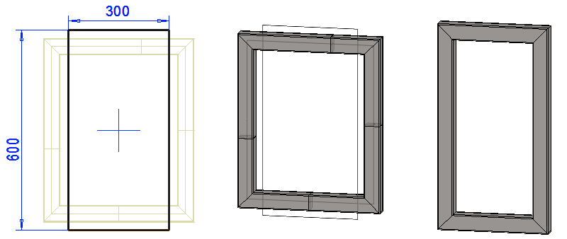
Edit the size of the frame
Edit guide curve part SKELETON:
-
Select the model SKELETON from the feature tree.
-
Right-click function: Edit.
-
Click the Guide Curve feature in the feature tree.
-
Right-click function: Edit sketch.
-
Change dimensions: 500 > 600 and 400 > 300.
-
Exit from the skecth: OK.
Exit from part to assembly: OK.
Update profiles to the dimensions of guide curve:
-
Right-click function: Solve.
Open the drawing and update it
-
You will see that the parts list information in the drawing will also change.
Save the model
-
File > Save or click
Download the frame model (VX_PROF1.vxz) here.