

Exercise 1: Corner joint
This exercise was carried out with version 27.0 (Vertex 2021).
In this exercise you will learn to
-
Repeat the sketching tools.
-
Select or specify the extrusion direction by dragging the arrow.
-
Feature mirroring.
-
How to add a library feature and its copies.
-
Edit an earlier feature.
-
Create rounds.
-
Select points and lines through the surface.
-
Geometry dimensional inspection.
Functions to be used:
-
New sketch to horizontal (XY) plane and to face
-
Sketching tools: Add lines and add constraints, e.g. Coincident, symmetry, distance, radius and diameter constraints.
-
Operation: Boss Extrusion and Cutout Extrusion. Extrusion: Flip Directions.
-
Add Round/Bevel > Round
-
Round point.
-
Mirror Feature.
-
Add cutout using feature from library and Add feature copy.
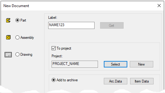
Create a new part
-
File > New > Part.
-
Enter the label (which is also the name of the model and by default will be the name of the drawing).
-
Enter the archive information by clicking Arc.Data.
-
Select the project where the model will be saved.
-
OK.
-
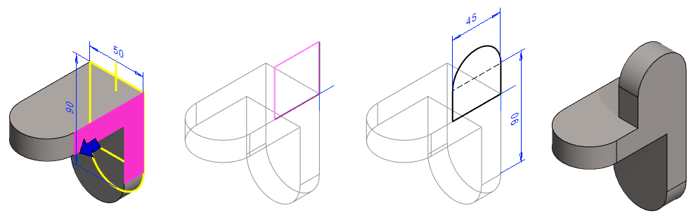
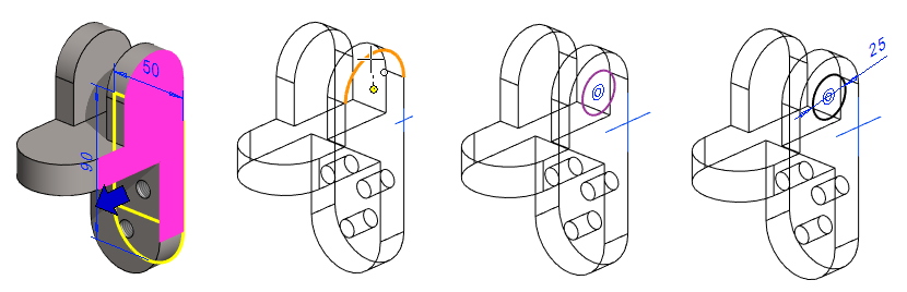
Create the first feature
-
New Sketch > To vertical (XZ) plane
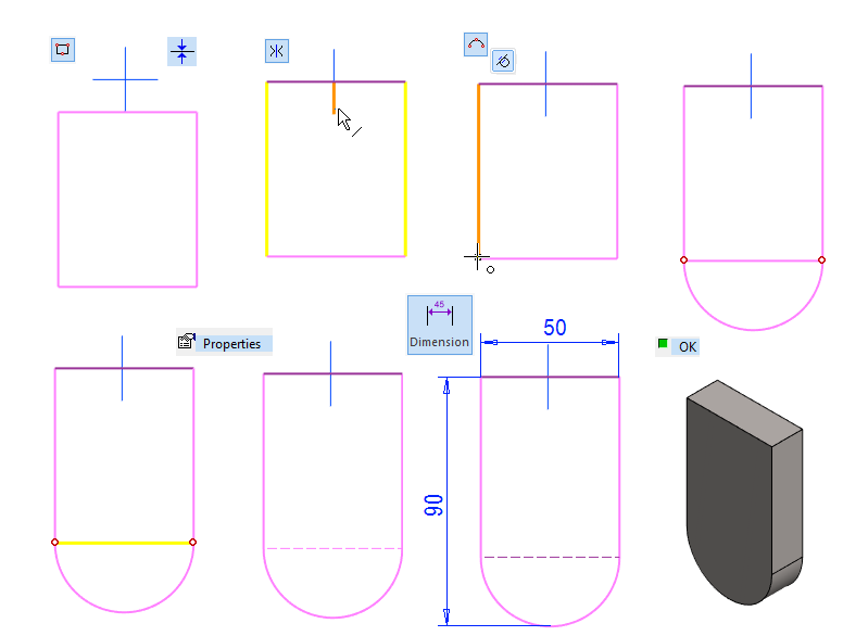
Sketch the shape
-
Sketch a rectangle.
-
Add the coincident constraint between the upper line and the horizontal line of the center cross.
-
Add the symmetry constraint to the vertical lines with respect to the vertical axis of the center cross.
-
Sketch an arc with the function: Acr with Tree Points.
-
If a tangentiality is not set, select it from the mini toolbar.
-
If the arc is drawn in the wrong direction, abort the operation and do it again so that the program indicates with an attention color that the vertical line and the end point will be selected.
-
-
Change the lower horizontal line to a construction line.
-
Click the line and Right-click function: Properties.
-
In the ribbon, click Style: Construction line.
-
-
Add dimensions to the sketch: 50 and 90.
-

Operation
-
Boss - Extrude
-
Length: 18.
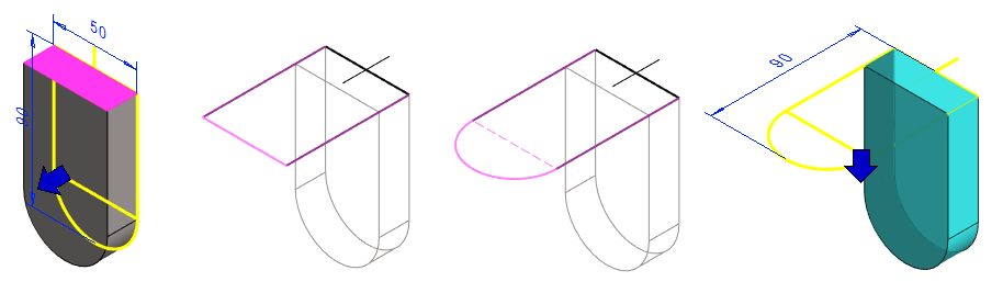
Create the second feature
-
Select the top face
-
Right-click function: New Sketch > To Face.
Sketch the shape
-
Sketch a rectangle.
-
Click the endpoints of the first line from the geometry.
-
Try dragging the vertical lines in the sketch. If they drag, add the necessary coinincident constraints between the sketch lines and the previous geometry.
-
-
Sketch an arc.
-
Change the lower horizontal line to a construction line.
-
Add dimensions to the sketch: 90.
-
Operation
-
Boss - Extrude
-
Length: 18.
-
Change the extrusion direction downwards or first pull the direction with the blue arrow and then enter the length.
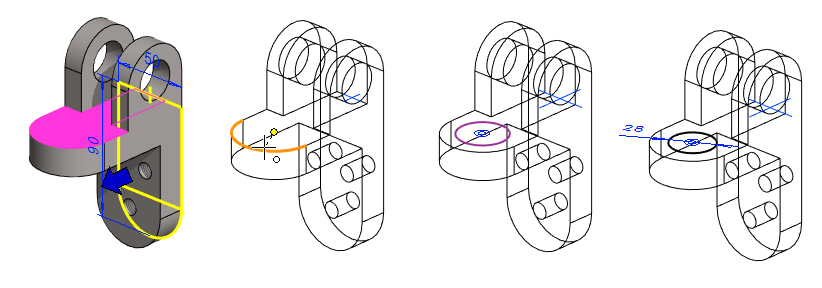
Create the third feature
-
Select the side face.
-
Right-click function: New Sketch > To Face.
Sketch the shape
-
Sketch a rectangle.
-
Click the first point to the origo.
-
-
Sketch an arc.
-
Change the upper horizontal line to a construction line.
-
Add dimensions to the sketch: 90 and 45.
-
Operation
-
Boss - Extrude
-
Length: 18.
-
Change the extrusion direction downwards or first pull the direction with the blue arrow and then enter the length.
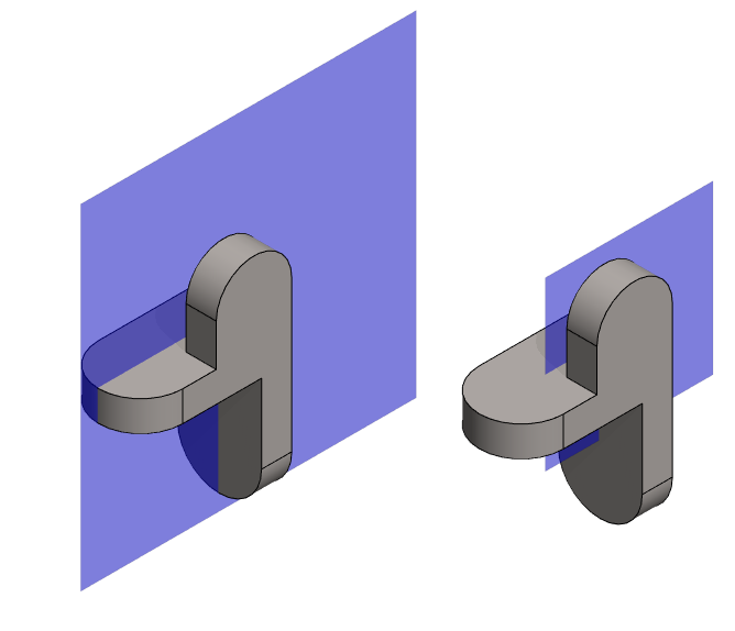
Resize the auxiliary plane
-
Restore the Lateral (YZ) plane from the feature tree if it is hidden.
-
Click the plane.
-
Right-click function: Change Size.
-
Enter the new value: 100.
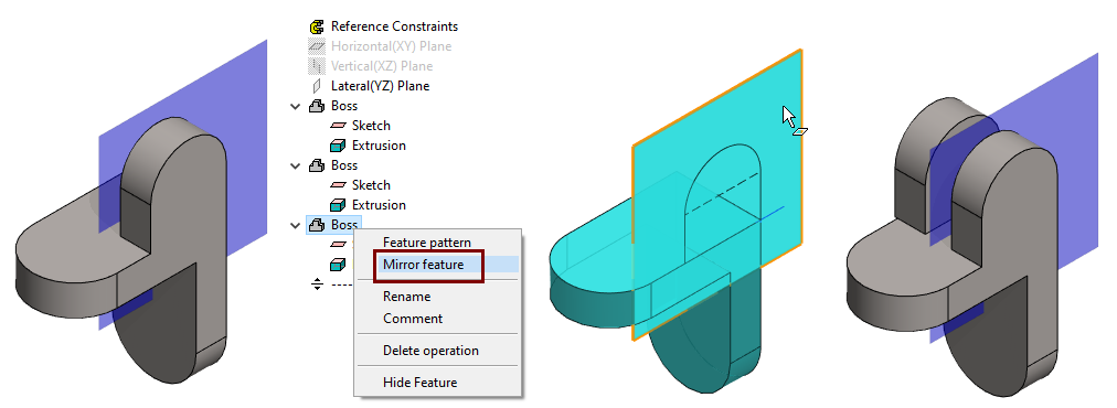
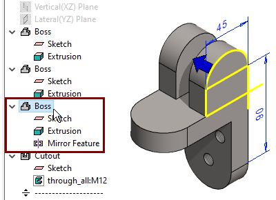
Mirror the second lug
-
Select a feature from the feature tree.
-
Right-click function: Mirror Feature.
-
Click the auxiliary plane.
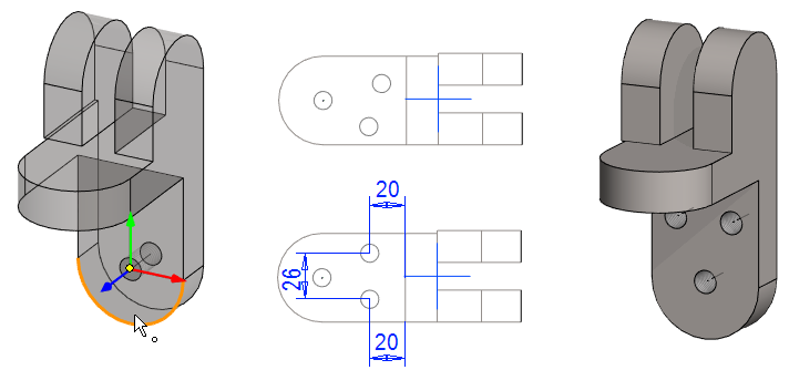
Insert the threaded holes in the bottom tab
-
Right-click function: Library feature > Cutout or function

-
Select the library feature in the browser: Library > Features > Thread > Metric > through_all.
-
Browse and select the size: M12.
-
Enter the hole length h: 18. (Because the thickness of the tab is 30mm.)
-
Enter the length of the thread section TL: 18.
-
-
Click the position of the first feature so that it comes to the front face and so that it finds the center of the arc (In this case, the feature is exactly in the right place)
-
You can also add the concentricity constraint later if the exact location pointing failed.
-
-
Right-click function: Add Feature Copy.
-
Add two copies.
-
Add a symmetry constraint between the copy features with respect to the axis of the center cross.
-
Dimension the location of the copies: 20 on the side edges and 26 between the features.
-
OK to implement the features.
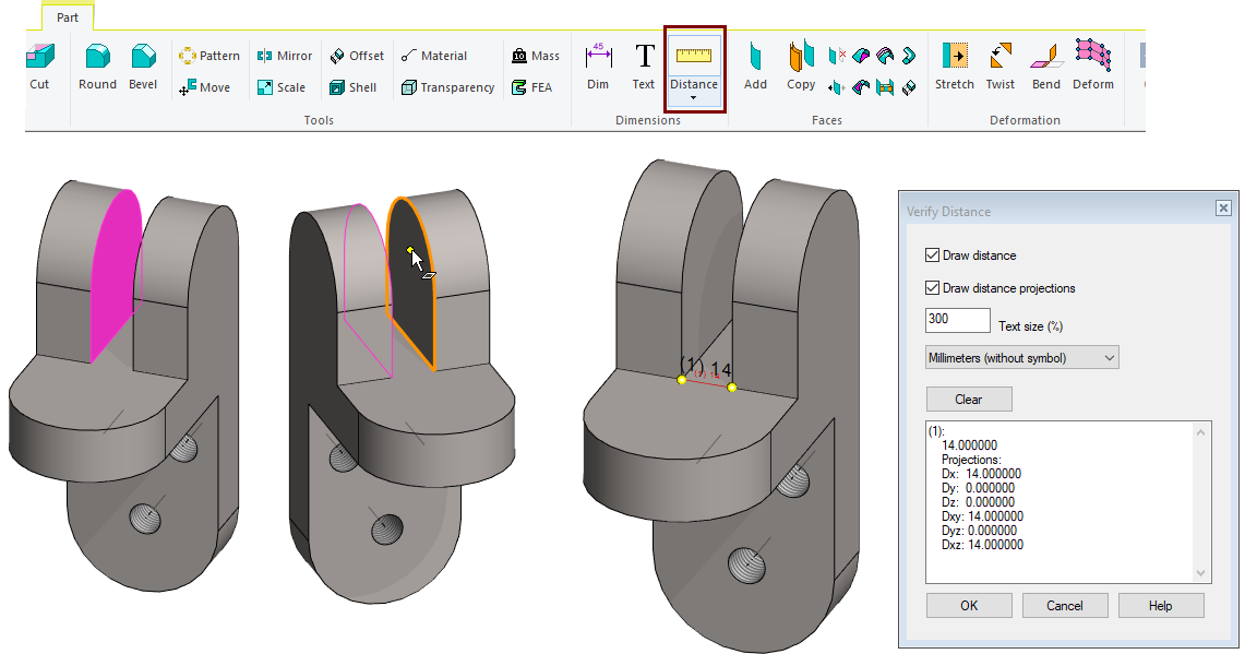
Check the distance between the lugs
-
The function: Distance. (Verify Distance)
-
Click to the first face.
-
Click to the second face.
-
If the dimension text is too small, increase it by giving a percentage value to the Text size field.
-
Note that the distance between the lugs is too small.
-
It should be 24 mm.
-
Change the thickness of the lug to be 13mm.
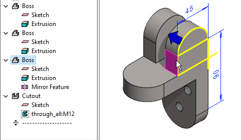
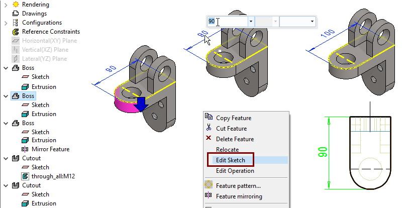
Find the feature you want to edit
-
Click to the surface that was created when the feature was created
-
The program shows the feature in the feature tree.
You can also select a feature or its sketch or operation from the feature tree.
-
The program marks the feature in the model.
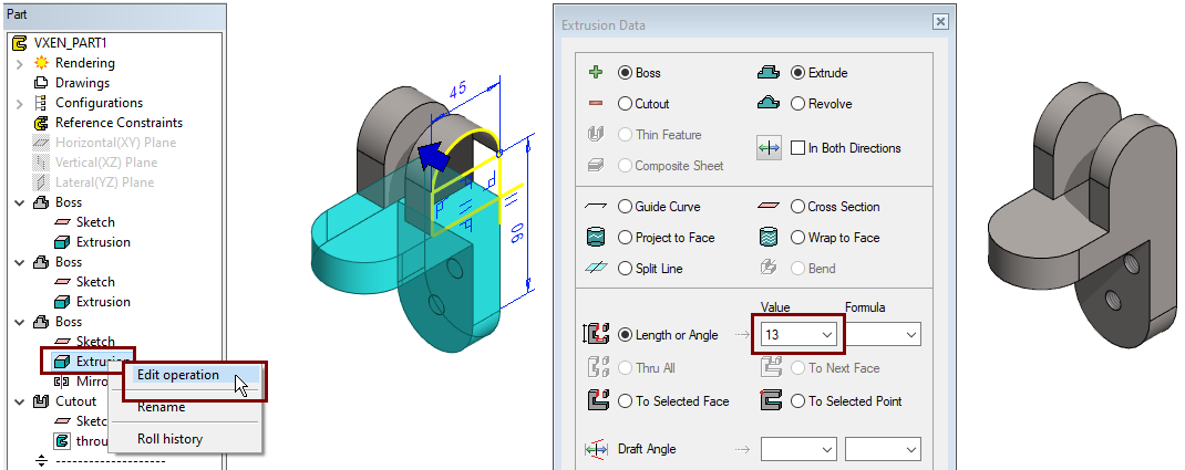
Change the thickness of the lug
-
Right-click function: Edit Operation.
-
Change the value from 18 to 13.
Create the holes in the lugs
-
Select the side face.
-
Right-click function: New Sketch > To Face.
Sketch the shape
-
The function: Circle. (Circle with Center and Radii Point).
-
Click the center of circle, the center point of arc or add a concentricity constraint later.
-
-
Add a Diameter constraint: 25.
-
Operation:
-
Cutout - Extrude - Thru all
Create the hole in the horizontal tab
-
Select the face of the tab
-
Right-click function: New Sketch > To Face.
Sketch the shape
-
The function: Circle.
-
Click the center of circle, the center point of arc or add a concentricity constraint later.
-
-
Add a Diameter constraint: 28.
-
Operation:
-
Cutout - Extrude - Thru all.
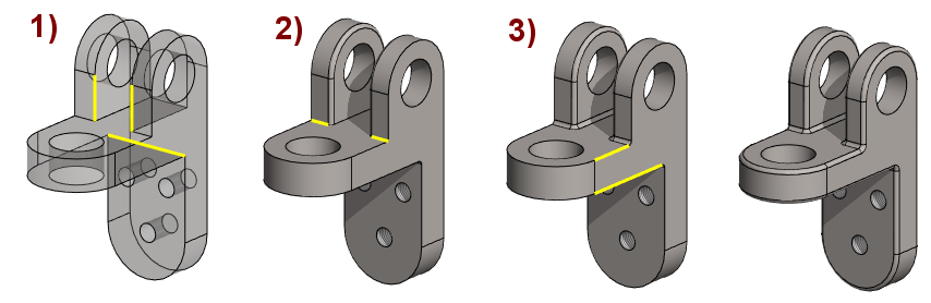
Change the length of the tab
The hole is too close to the lugs. So the length of the tab needs to be changed.
-
Click the surface that was created when the feature was created.
Resize, method 1: (Figure series in the top row)
-
Choose the right feature
-
Select dimension 90.
-
Change the dimension from 90 to 100 with the Mini Toolbar shown in the figure.
Resize, Method 2: (Figure series in the bottom row)
-
Choose the right feature
-
Right-click function: Edit Sketch.
-
Select dimension 90 and change value to 100.
-
OK. (exits the sketch and changes the template).
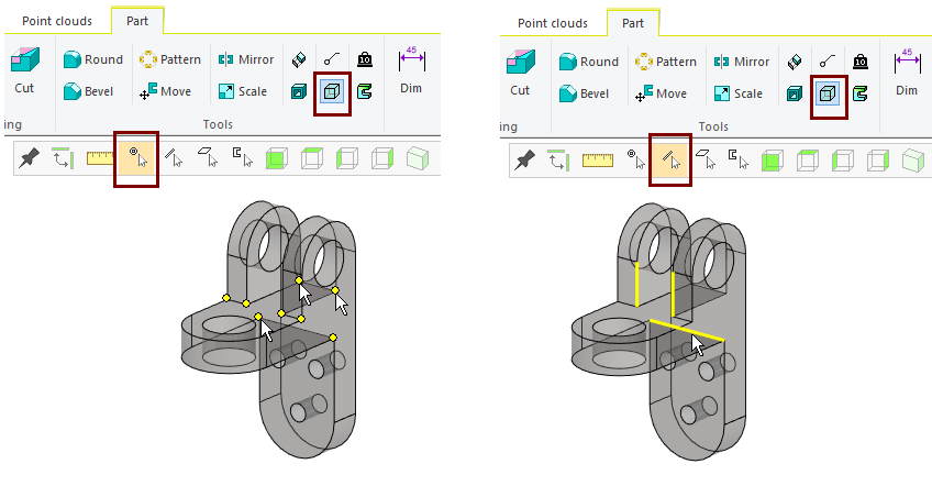
Add roundings
-
All sharp corner points are first selected as shown in the figure on the right.
-
Then Right-click function: Round point.
-
Enter the rounding, e.g. 2.
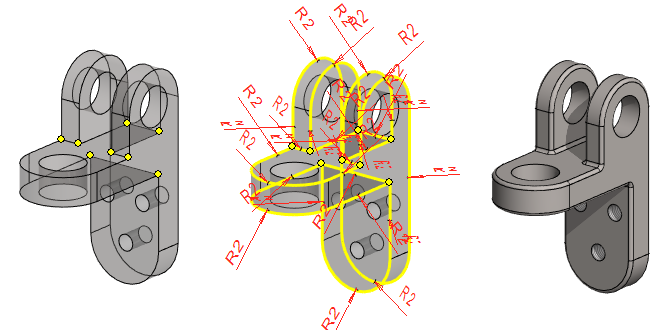
An alternative way to do rounding in several steps
-
This is used if any roundening is different from other roundenings.
If you are rounding with the Add Round/Bevel > Round function, you should think about rounding so that the next round can proceed "forward as a chain". See picture on the right.
-
Click one or more lines.
-
Right-click function: Add Round/Bevel > Round.
When you select transparency
-
If only the selection Snap to Point is selected, you can click points that are behind the surfaces.
-
If only the selection Snap to Line is selected, you can click lines that are behind the surfaces.
Save the model
-
File > Save or click


Further processing of the model (These are presented in Exercise 5 "Drawing on model")
You can add a material item to the model with the right-click function Item Data.
-
These will also appear in the parts list of the model drawing.
You can create a drawing for the model.
-
In the feature tree, select Drawings.
-
Right-click function: New Drawing.