

Exercise 1: How to use the constraints of the assembly
In this exercise, components are added and positioned relative to each other, giving constraints between them.
-
The components are used because they are also found on a newly installed system that does not have archived models.
-
In some later exercises, the parts are first modeled or the parts needed for the exercises are retrieved, from which assemblies are then assembled.
This exercise was carried out with version 27.0 (Vertex 2021).
In this exercise you will learn to
-
Hiding and restoring auxiliary plane of assembly.
-
To add parts to the assembly from the component library.
-
To locate parts with each other using constraints.
-
To drag parts that are either limited by the constraints or not.
-
Check the effect of the constraints.
-
Dynamic and static collision analysis.
-
Distance constraint side shift.
Functions to be used:
-
File > New > Assembly.
-
Add > Component.
-
Add coincidence constraint.
-
Add distance constraint.
-
Add tangential constraint.
-
Distance > Change side.
-
Collision Detection > Static.
-
Collision Detection > Dynamic.
-
(Auxiliary plane of Feature Tree) > Hide / Restore.
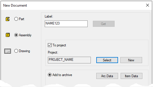
Create a new assembly
-
File > New > Assembly.
-
Enter the label (which is also the name of the model and by default will be the name of the drawing).
-
Enter the archive information by clicking Arc.Data.
-
Select the project where the model will be saved.
-
OK.
-
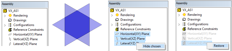
Hide or restore auxiliary plane of assemblies.
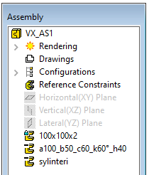
The feature tree of the assembly has similar auxiliary planes as the part models.
-
Hide auxiliary plane or planes with right-click function: Hide or Hide chosen.
-
Use the right-click function to restore the auxiliary plane or planes: Restore or Restore chosen.
You can use the auxiliary planes of assembly for locate parts. Auxiliary planes were introduced in assemblies in version 25.0.00 (Vertex 2019).
-
Until version 24.0.XX (Vertex 2018), the locking of the part first introduced into the part model was used to position other parts. This is still available, but parts can also be tied to assembly auxiliary levels, so that the first added part can either be removed or removed without the other parts coming off (Of course, provided they are tied to assembly auxiliary planes).
-
Click an auxiliary plane from feature tree (Not from model).
-
Right-click function: Changer size.
-
Enter the size.
Edit system settings (This affects all users using the same Vertex G4 file server).
-
File > System Preferences > Edit > Administrator's view > 3d group.
Keyword: baseplanesvisiblewhencreated.
-
0 = Auxiliary levels hidden in part and assembly models when a new model is created.
-
1 = Visible in the part model.
-
2 = Visible in the assembly model.
-
3 = Both visible (default)
Add three components
-
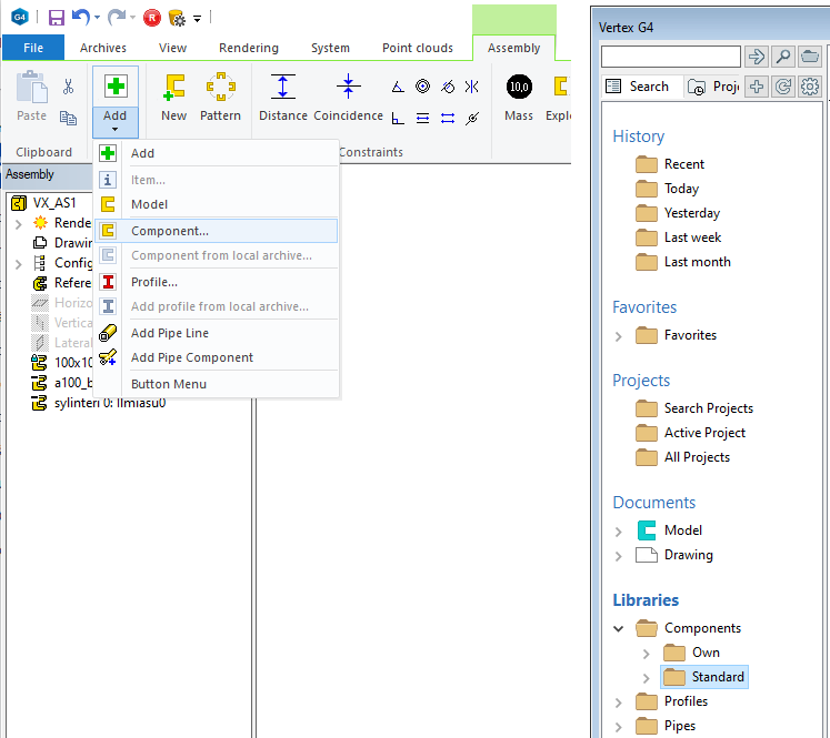
Right-click function: Add > Component.
-
Select: Standart > Basic_Shapes > rectangle.
-
Enter dimensions:
-
a: 200, b: 100, h: 10
-
OK.
-
Use the right-click function OK or V key to place the first part in assembly.
-
This drops part of its own origo to the origo of the assembly.
-
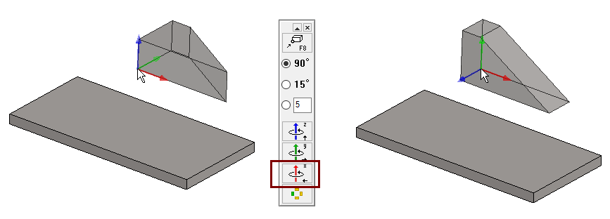
Add a trapezoid.
-
a: 100, b: 20, c: 50, h: 30 and k: 90.
-
Rotate part wiht the Rotate around X-axis button once, when the rotation angle is 90 degrees.
-
-
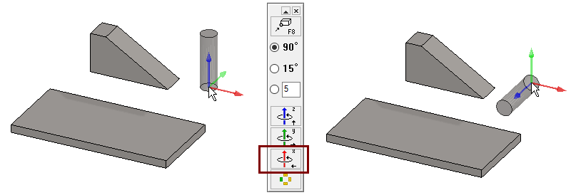
Add a cylinder.
-
D: 20, h: 70.
-
Rotate part wiht the Rotate around X-axis button once.
-
Assembly Ribbon has Add button. Objects can also be dragged into the assembly from the B browser
Freely variable components appear in the feature tree either by file name or, if dimension table information is stored for the component, by the title of the selected dimension table row, even if the dimensions of the component itself differ from these dimensions.
For this reason, for freely variable components (such as a rectangle and a trapezoid), no rows should ever have been added to the dimension table.
-
Keep this in mind when modeling components for yourself.
Drag the parts
-
Select a part and hold down the mouse selection button and drag the part.
-
You cannot drag the first part as it is fixed in place. The fixing is indicated by a blue lock on the part symbol.
-
-
The other parts drag freely.
Because dragging occurs only in the image plane, you can make it easier to roughly position a part by using the toolbar to reverse the viewing direction of the workspace and then dragging the parts again.

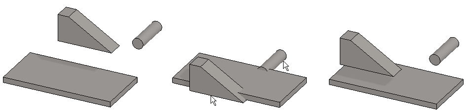
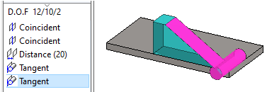
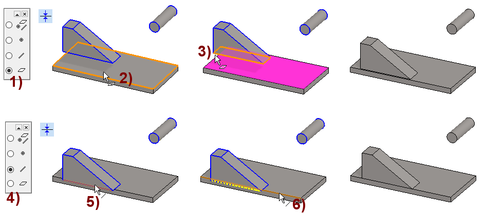
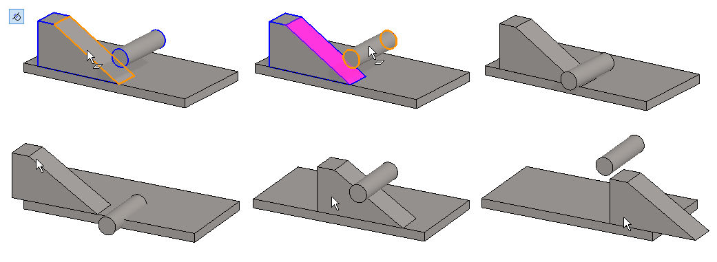
Add two coincidence constraints between the rectangle and the trapezoid.
-
Function (In the Ribbon): Coincidence (Add coincidence constraint).
-
The program draws with a blue border the parts that are not fixed or that still have degrees of freedom due to lack of constraints.
-
-
Be sure, that Snap to face is selected in the auxiliary menu. In the figure 1).
-
Click on the face from the first part, in the figure 2).
-
Click on the face from the second part, in the figure 3).
-
You either have to flip the model or click "a little past the edge" to hit the hidden face, but so that there are no other faces under the cursor.
-
-
Switch from the auxiliary menu to Snap to line, in the figure 4).
-
Click on the line from the first part, in the figure 5).
-
Click on the line from the second part, in the figure 6).
-
Stop adding constraints with the Ready command:
-


-
Try dragging the trapezoid
-
The trapezoid slides like on rails while maintaining its direction.
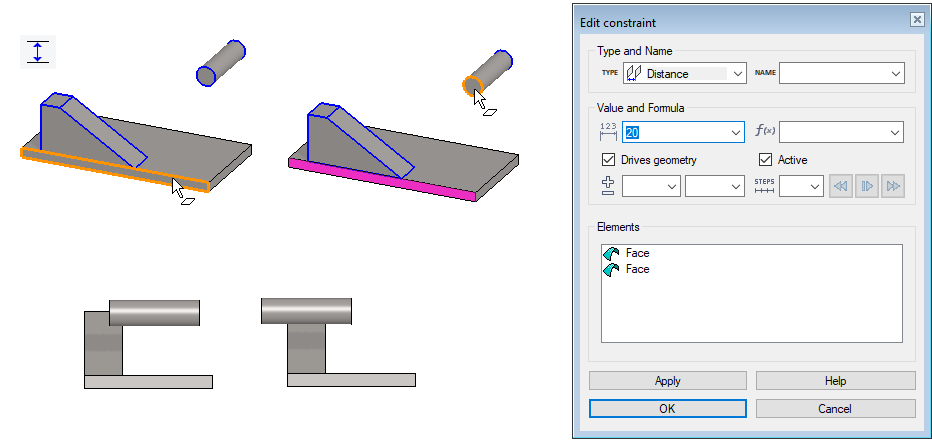
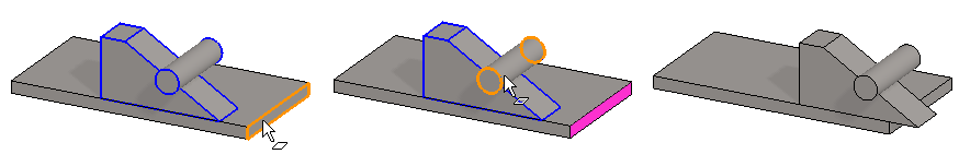
Add a distance constraint between the cylinder and the rectangle.
-
Function (In the Ribbon): Distance (Add distance constraint).
-
Be sure, that Snap to face is selected in the auxiliary menu.
-
Click on the face from the first part.
-
Click on the face from the second part.
-
The program opens the dialog Edit Constrain
-
Enter the distance value: 20.
-
Depending on the location of the part before the constraint is given, the end result can be two options (bottom image).
-
-
Stop adding constraints with the Ready command:
-
-
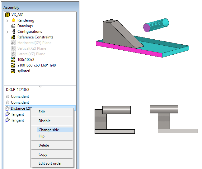
Change the side of the distance constraint.
-
Select a distance constraint (below the feature tree) from the list of constraints.
-
The program paints parts of the workspace in blue and red on the affected faces.
-
-
Right-click function: Change size.
-
Leave the cylinder in the position to the right of the lower figure.
Add a tangential constraint between the cylinder and the trapezoid
-
Function (In the Ribbon): Add tangential constraint.
-
Be sure, that Snap to face is selected in the auxiliary menu.
-
Click on the face from the first part.
-
Click on the face from the second part.
-
Stop adding constraints with the Ready command:
-
-
Try dragging the trapezoid
-
The trapezoid continues to slide while maintaining its direction and the cylinder moves up and down following the oblique surface of the trapezoid.
-
You can also drag the cylinder, as its position in the X-axis direction is not limited by any constraint.
Add a tangential constraint between the cylinder and the end of the rectangle.
-
Click on the face from the first part.
-
Click on the face from the second part.
-
Try dragging parts
-
The trapezoid continues to slide while maintaining its direction and the cylinder moves up and down following the oblique surface of the trapezoid.
-
You can also drag the cylinder, as its position in the X-axis direction is not limited by any constraint.
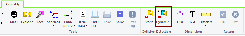
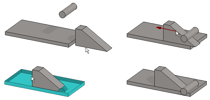
Select dynamic collision detection
-
First, drag the parts to a position where the cylinder and rectangle are not nested.
-
Function: Dynamic (From the Assembly ribbon, in Collision Detection group.)
Try dragging the trapezoid
-
Dragging succeeds until the partds collide and stop there.
-
The program stains colliding parts with a blue attention color.
Dynamic collision detection takes computer resources.
-
For this reason, the Dynamic collision detection should not be left on in larger models, because it will slow down the start of the drag function as well as draging.
View collisions at any time
-
Function: Static (From the Assembly ribbon, in Collision Detection group.)
Save the model
-
File > Save or click


Download the XXXX model (VX_AS1.vxz) here