Use MEP IFC Models to Modify Framing
IFC files are typically split to different disciplines, for example:
Architectural
Structural
Mechanical, Electrical and Plumbing (MEP)
You can import each IFC model seperately and use each one in different ways.
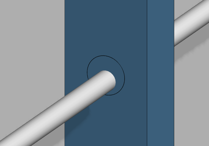
Example - A building has a structural steel layout, the architectural model defines the walls in between the structural steel frame. These walls are timber or light gauge steel framing system. Finally, plumbing runs through the framed studs and/or joists. Where a pipe clashes with a stud or joist a service hole is required to be punched and we can use the MEP model to automatically create these holes.
IFC MEP objects are described as IFCFlowSegments. A pipe itself is described as Flow Segment.
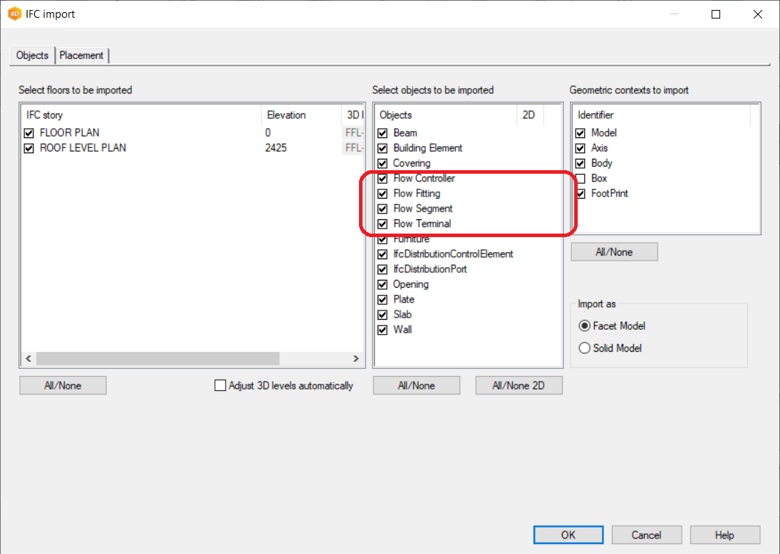
In this example we look at a bathroom pod.
Import your architectural IFC models into your project, convert to Vertex parts and generate the framing. Then import your MEP model into the framing drawing-model pair.
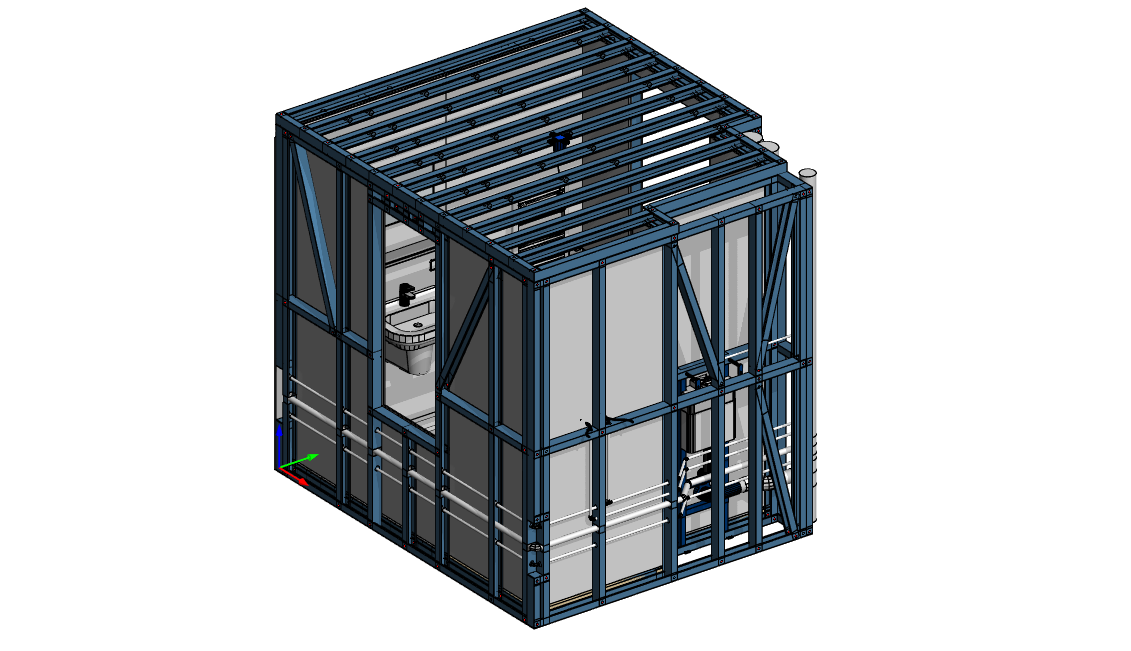
Use the selection filter to find and filter by pipes of a certain size either by choosing Flow Segments (IFC) or by the IFC attribute filter. Press CTRL+A to select all the pipes based on that filter.
Right-click and choose Add Punch to Structure.
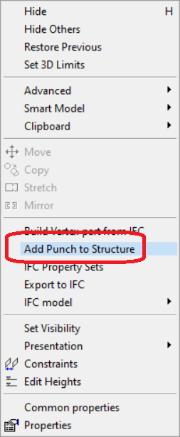
Press CTRL+A to select all panels or pick the only panels you want to affect manually holding down CTRL key and clicking on the panels. Select Confirm.
A list of pipes and their suggested hole size will appear. For timber users the hole size can be any size, but steel users must pick a hole size that is setup up for their roll forming machine (Howick/Pinnacle), for example 34.1 mm.
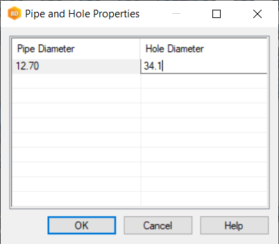
Give the wanted hole sizes and confirm. The studs/joists will now have that hole punched.
