
The Truss Engineering area of Vertex BD has seen extensive improvements in the new 2018 release.
This guide will help with explaining the new functionality and changes that have been made and how they can be used to improve and expedite the truss design and engineering process.
General
There has been much focus on improving speed and user interface in Vertex BD 2018. New functionality has been introduced to allow “single truss engineering” which provides the detailer with the tools to focus on “one truss” at a time when trying to resolve design issues. This reduces the time factor considerably, as the entire model does not need to be re-engineered each time a change is made and small changes can be made and tested quickly to optimize the design and reduce the amount of “steelwork” for each truss. This will result in cost savings for the workshop in assembly time and materials, reduced transport costs and reduced detailing time for the design office.
“One Truss Engineering” (Locating & fixing issues, modifying & optimizing truss design)
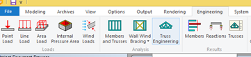
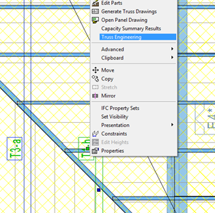
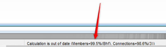
More functionality and new interfaces have been developed to enable the detailer to locate and resolve issues in truss design. Once the initial “whole roof” engineering check has been run, the results box will be presented. All warnings and errors can be individually clicked on and the location will be displayed in the model views. Depending on the particular error, the member, joint or area will be indicated by a flashing arrow. To investigate more deeply you can use “One Truss Engineering” which you open by clicking on the “Truss Engineering” button on the ribbon bar or the right click menu.
This will open a new window which will display the truss with all the loads and supports and will indicate which members are failing, where they are failing and the deflection values of the bottom chord. You will also see an “Overall Design Result” at the bottom of the screen which will display the worst case percentages for members and connections.
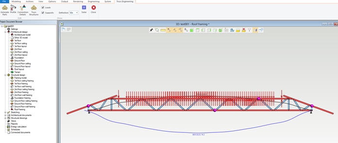
You can use the “Generate Parts” button to re-generate the parts of the truss, change member sizes, modify web spacing and positions. You can use the “Truss structures” button to “box” members and the “Connection Details” button to add splices or brackets.
You can then click the “Solve” button which will run engineering on just that truss using the loads that were previously assigned to it. This process has been streamlined greatly and is very fast. You will get a results box when this is finished and you can make further changes and test again until you have optimized the truss. You can see by the “overall design result” how close the truss is to failing so you can push your design to the limit.
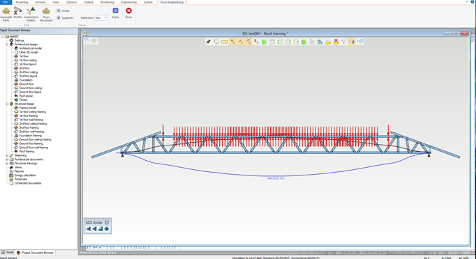
The bottom chord deflection value can also be used to ensure that the deflection differential between adjacent trusses is not too great to avoid ceiling issues.
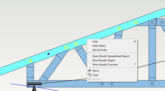
Each member in the truss can be interrogated further by displaying
-
Results Spreadsheet
-
Results Graphs
-
Results Overview
The “One Truss Engineering” view is directly linked to the model so you can make any manual changes to the truss that you want and test the results.
Once all the individual trusses have been optimized and have passed you will need to run engineering on the whole roof again to ensure that individual changes do not impact on the adjacent trusses or the whole roof design.
Once all trusses are passing, engineering results drawings can then be produced.