Truss engineering errors and warnings
Warnings
Note
Warning messages serve as a calculation note to engineer. They should be carefully examined. However, they do not block truss engineering.
Hole or notch not included in design!
This warning message is included in all truss engineering results. It means that the existence of geometrical discontinuity like notches in materials will lead to strength weakening, as a resultant of local stress concentration, these weakening are taken care only in our tension check, but not in other checks.
Example:
For swage joints between the chords and webs, the lips notches are replaced by the inserted flanges of the webs, which will stiffen the flanges of the chords. Therefore, the chords can still be regarded as continuous.
Horizontal loads are not transferred between structures! Use bracing and battens to carry horizontal loads.
Only vertical loads are considered in Vertex BD truss engineering. the effect of horizontal loads should be considered by an engineer. For example, the loads transferred between hip trusses are not checked in truss engineering.
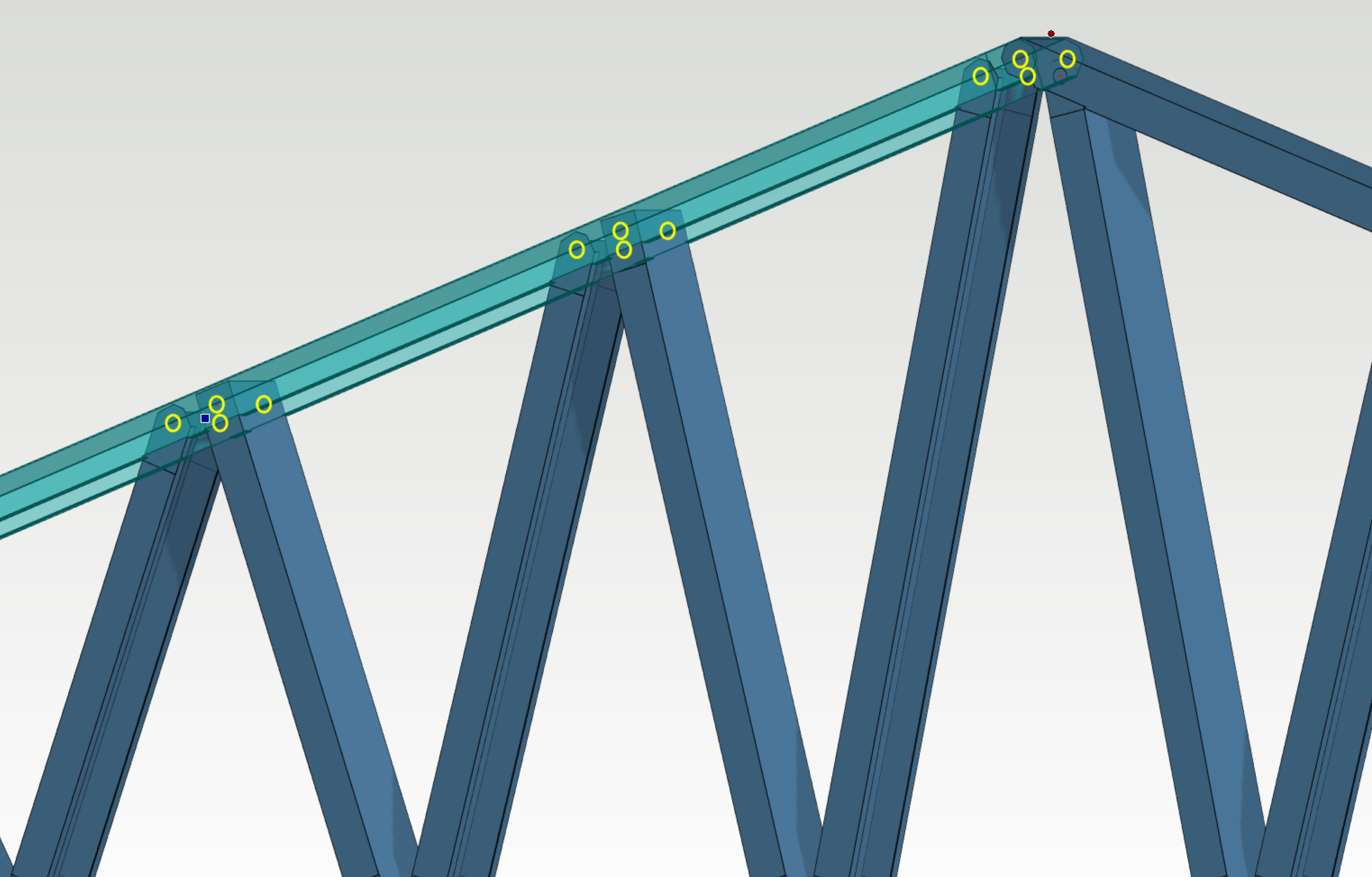
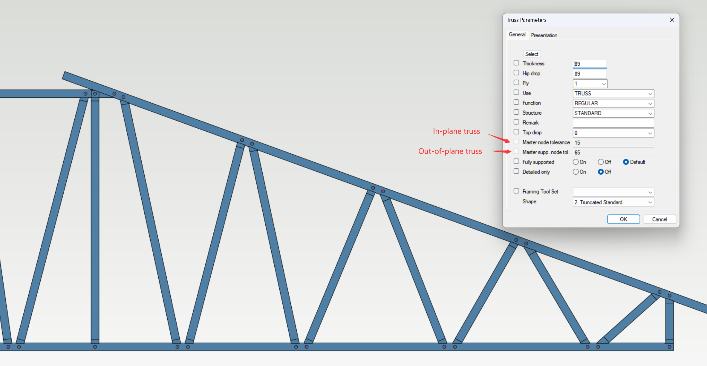
Possible truss triangulation problem detected. Chord may be subject to extra bending moment.
This warning message indicates that when the min node distance in truss web ends is smaller then the master node tolerance, two separated master nodes would be generated in the analysis model. In this case, the chord member would take bending moment and shear force. For in-plane trusses, the default master node tolerance is 15 mm; while the number is 65 mm for out-of-plane trusses. This value can be adjusted in vxsettings. Please consult Vertex support team if you wish to change this value.
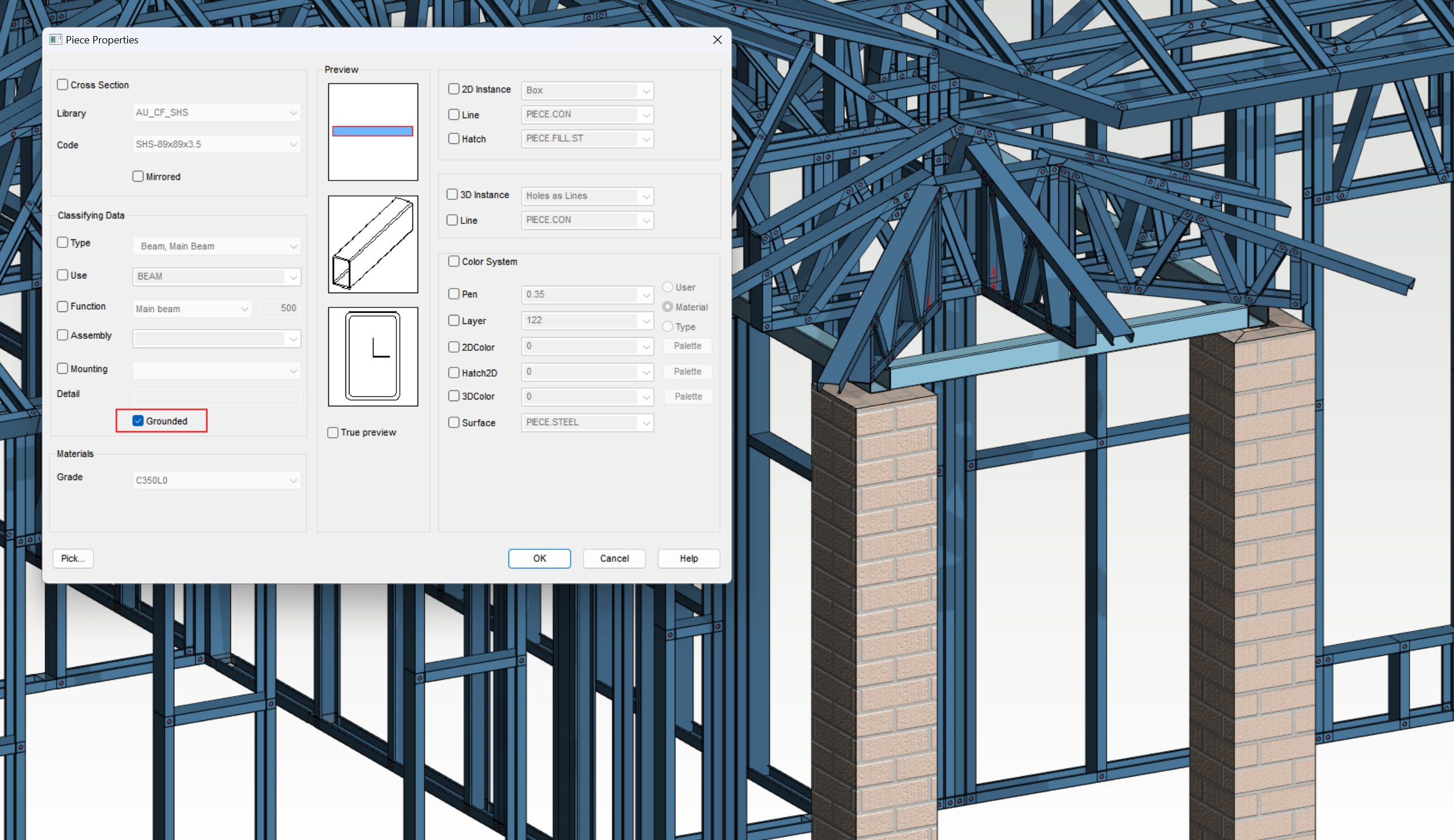
Grounded member detected. Reactions are not transferred to objects below.
If "Grounded" is checked for a bearing structure, this warning message will appear. Engineer would need to make sure that the grounded structure is sufficiently supported.
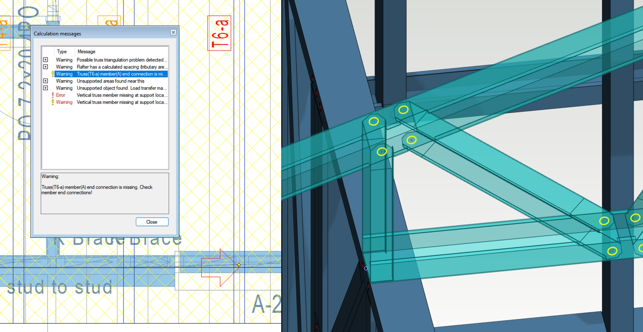
Truss members end connection is missing. Check member end connections!
This warning message points at missing connection in between two truss members. Truss engineering can still analyse the truss with the missing connection but it will be very likely that the truss members would fail due to not being sufficiently supported.
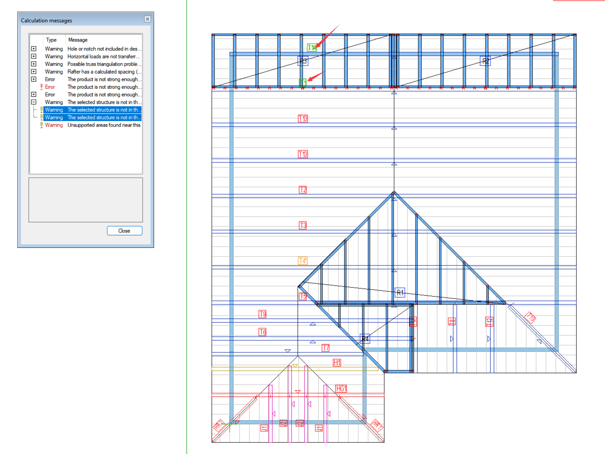
The selected structure is not in the load path. The structure is not analyzed. Add a support under the structure or add another structure on top it.
This warning message would appear after the truss engineering is finished. It indicates that the highlighted structure is not taking loads from any loading planes. The structure with this warning message would not be engineered until the structure is in the load path.
Example:
The two trusses under the gable ladder are not in the load path. This is the case because the members in the gable ladders were created using the common roof panel framing tools and the rafters are not transferring loads to the trusses.
The issue can be resolved when the correct framing tool is used for the roof gable ladder panels.
Errors
Note
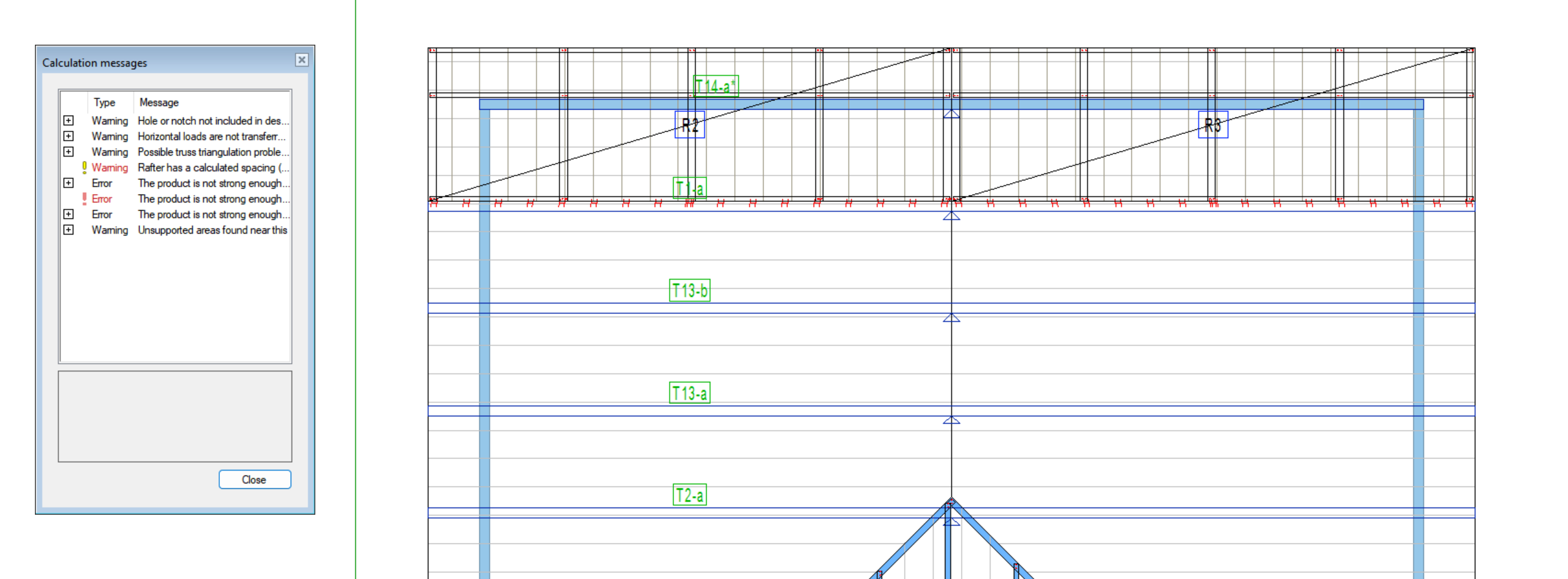
Error messages indicate that there are major issues with the truss model. These messages may occur before truss engineering can be performed (before Design Criteria dialogue), which indicates that the truss model is not ready for truss engineering. Modification to the boundary conditions is necessary depending on the type of message. If these messages appear after truss engineering is finished, it normally indicates that the truss structures failed capacity check.
The product is not strong enough for this application; change either the application or the product or both. Xxx design error.
This error indicates that the target structure failed truss engineering. The latter half of the error indicate the nature of the failure. Please investigate and trouble shoot the failure in Single truss engineering tool.
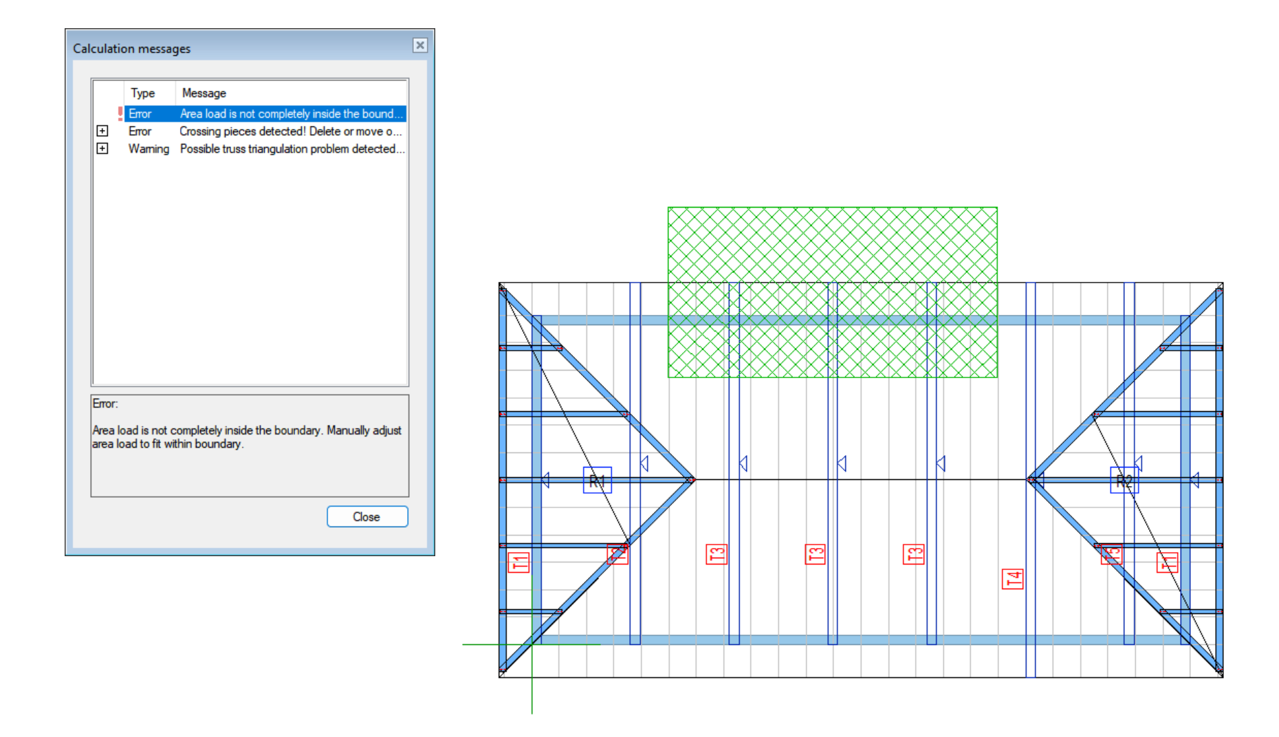
Area load is not completely inside the boundary. Manually adjust area load to fit within boundary.
This error occurs when the target area load is outside of the master plane. Move the area load back to inside of the master plane boundary will resolve the error.
Hint
The edges of the loaded plane need to be aligned to the x and y axis. If they are not, it may cause wind loads to have the above-mentioned error.
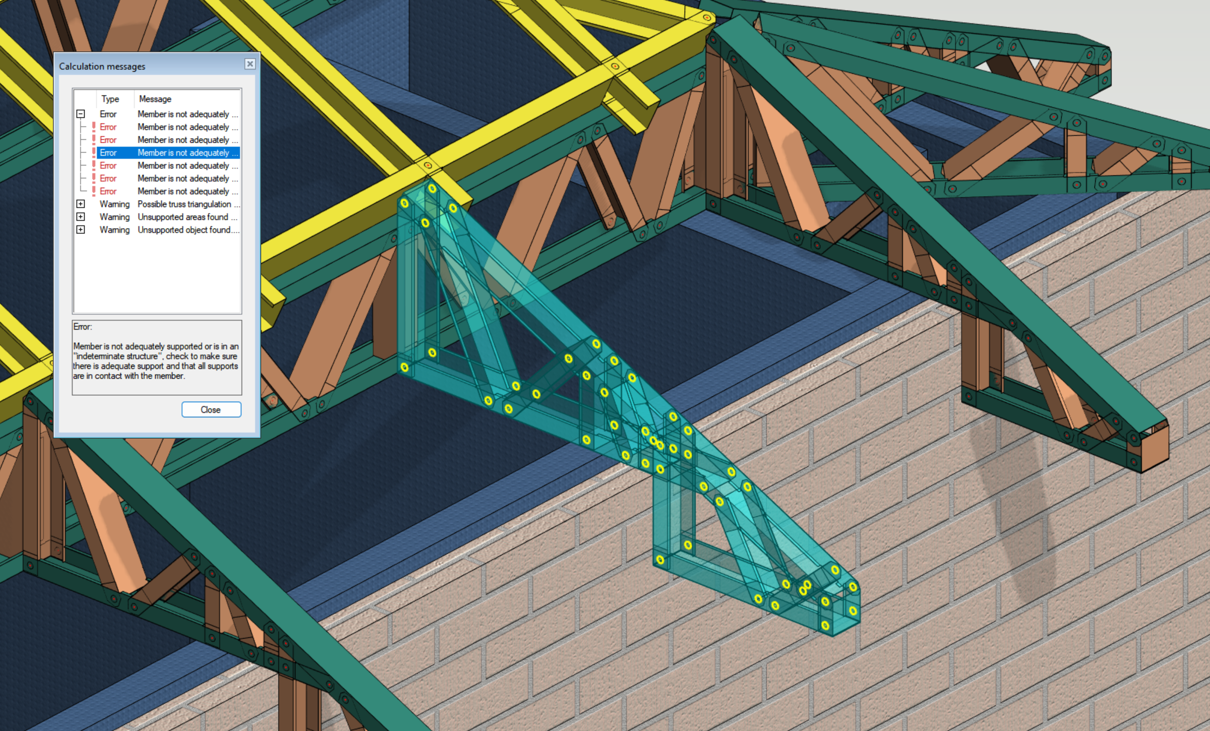
Member is not adequately supported or is in an “indeterminate structure”, check to make sure there is adequate support and that all supports are in contact with the member.
This error occurs when the structure is not sufficiently supported. All trusses should have at least two point supports or one continuous support.
Example:
The error points at the Jack trusses.
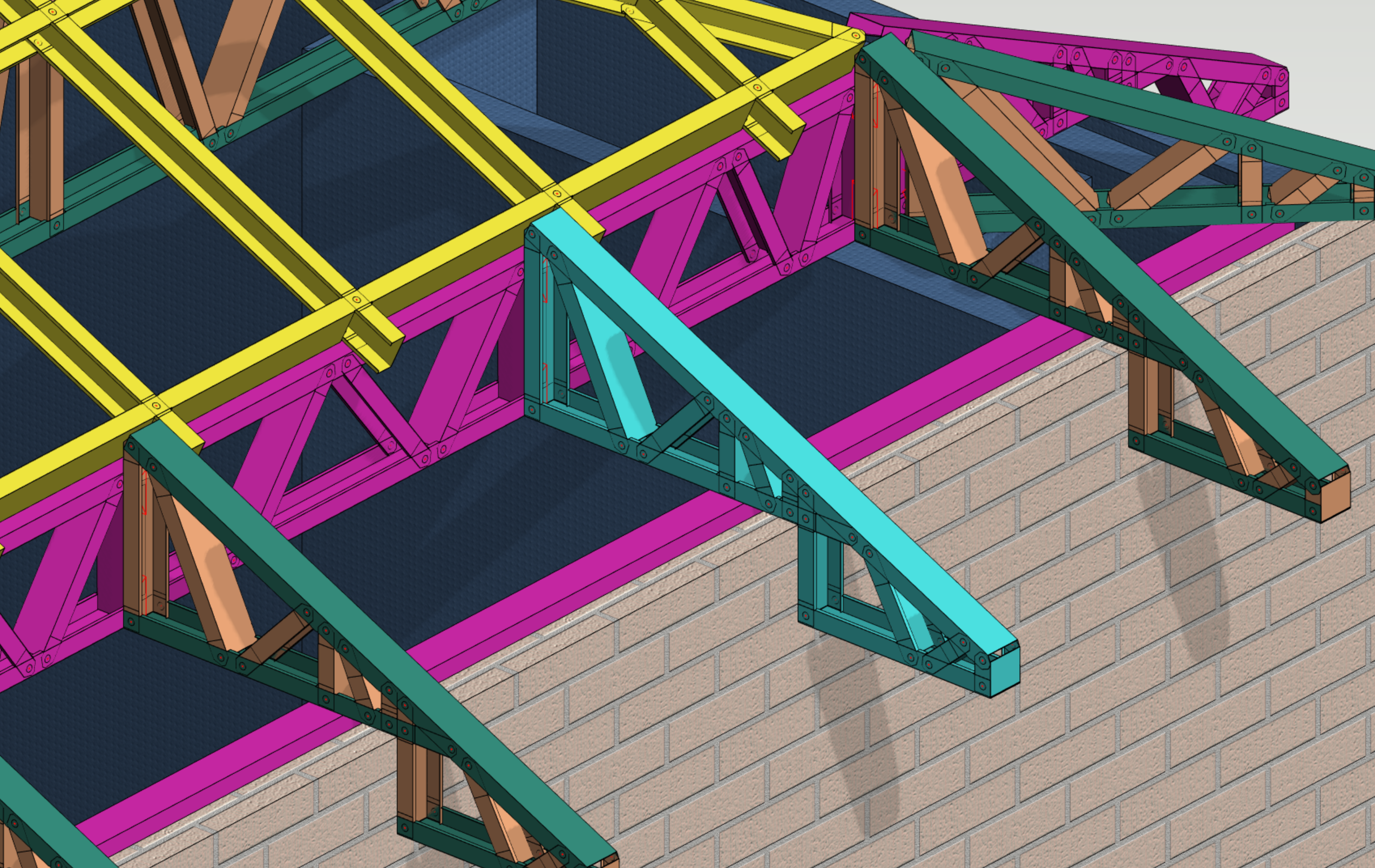
To resolve the error, direct screw connections were added between the Jack truss and the girder truss. Support for the Jack truss now come from both the exterior wall and the girder truss. Screenshot shows the bearing components in purple.
Hint
Supporting relationship can be checked using Bearing of Structures tool.
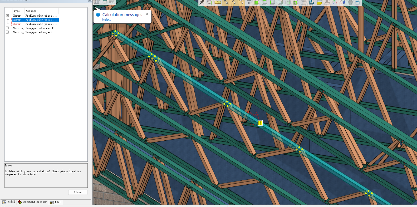
Problem with piece orientation! Check piece location compared to structure!
This error occurs when the load path from the architecture roof to the truss framing members is incomplete. It often means that the top chord is not aligned correctly with the roof plane.
Example:
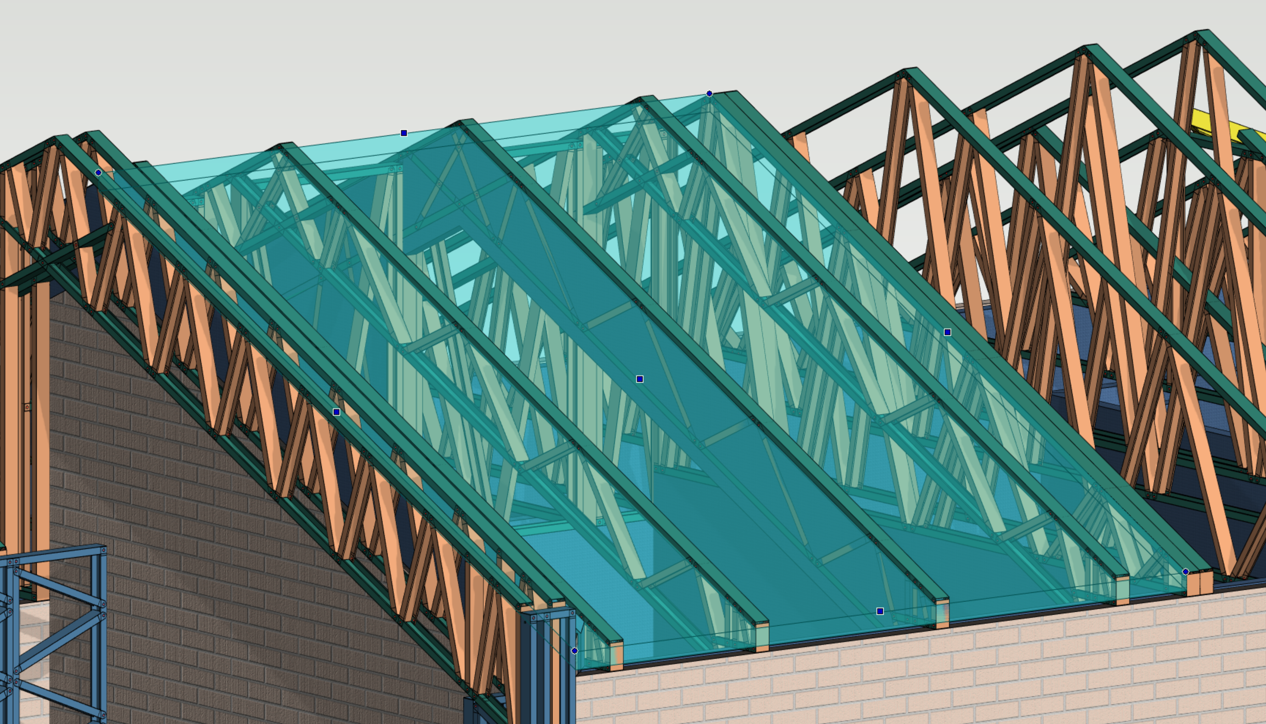
The errors pointed at the top chord of the scissor trusses.
Screenshot shows that the truss top chords were slightly above the roof plane. Errors were resolved after user moved the truss top chords down so that they were flush with roof plane.
Area load should be in same drawing model pair with horizontal structure.
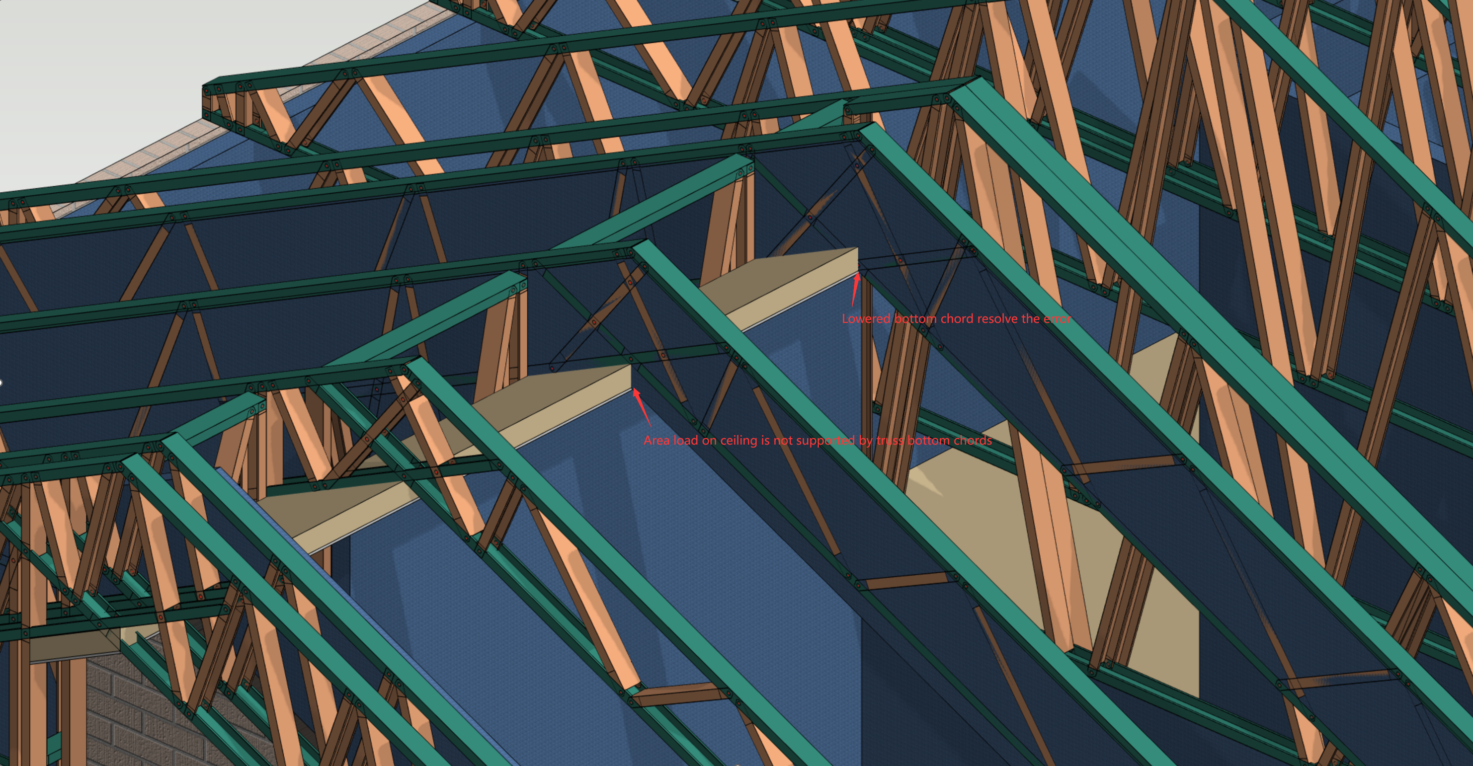
This error often comes with Unsupported object found error. In this case the area loads are not properly supported by the truss structures. User needs to make sure the added loads are in contact with valid loading planes and truss members.
Example:
Errors point at the internal wind pressure loaded on the racked ceiling.
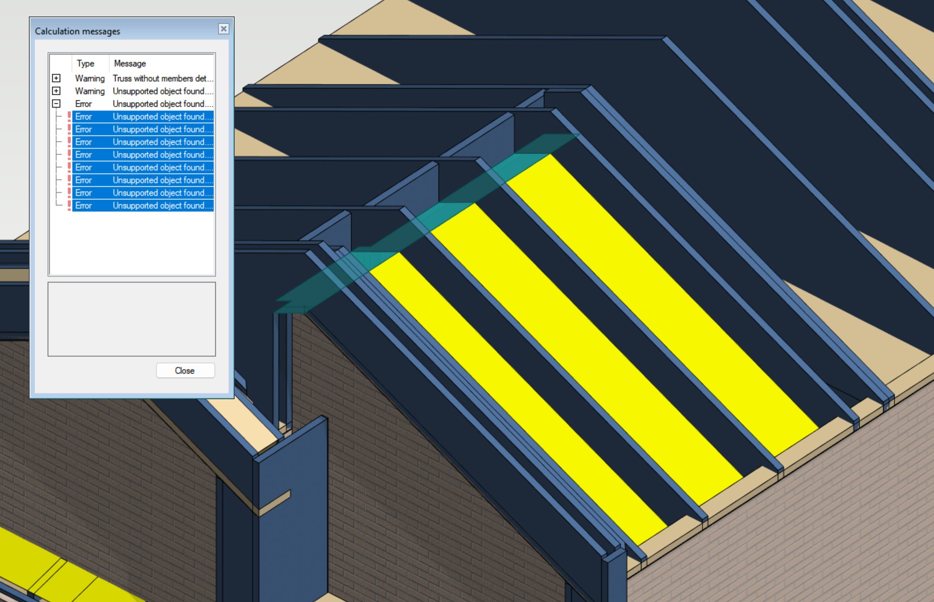
Error occurred because the bottom chords of the trusses did not meet the area load. The error can be resolved by moving the bottom chords so that they are flush with the plane of load.
Structure is mechanism
This error is from FEA analysis. It means the boundary condition of the object of design is not correctly defined and the analysis can not be performed. If it appears in truss engineering, it normally indicates that certain roof panel is not sufficiently supported.
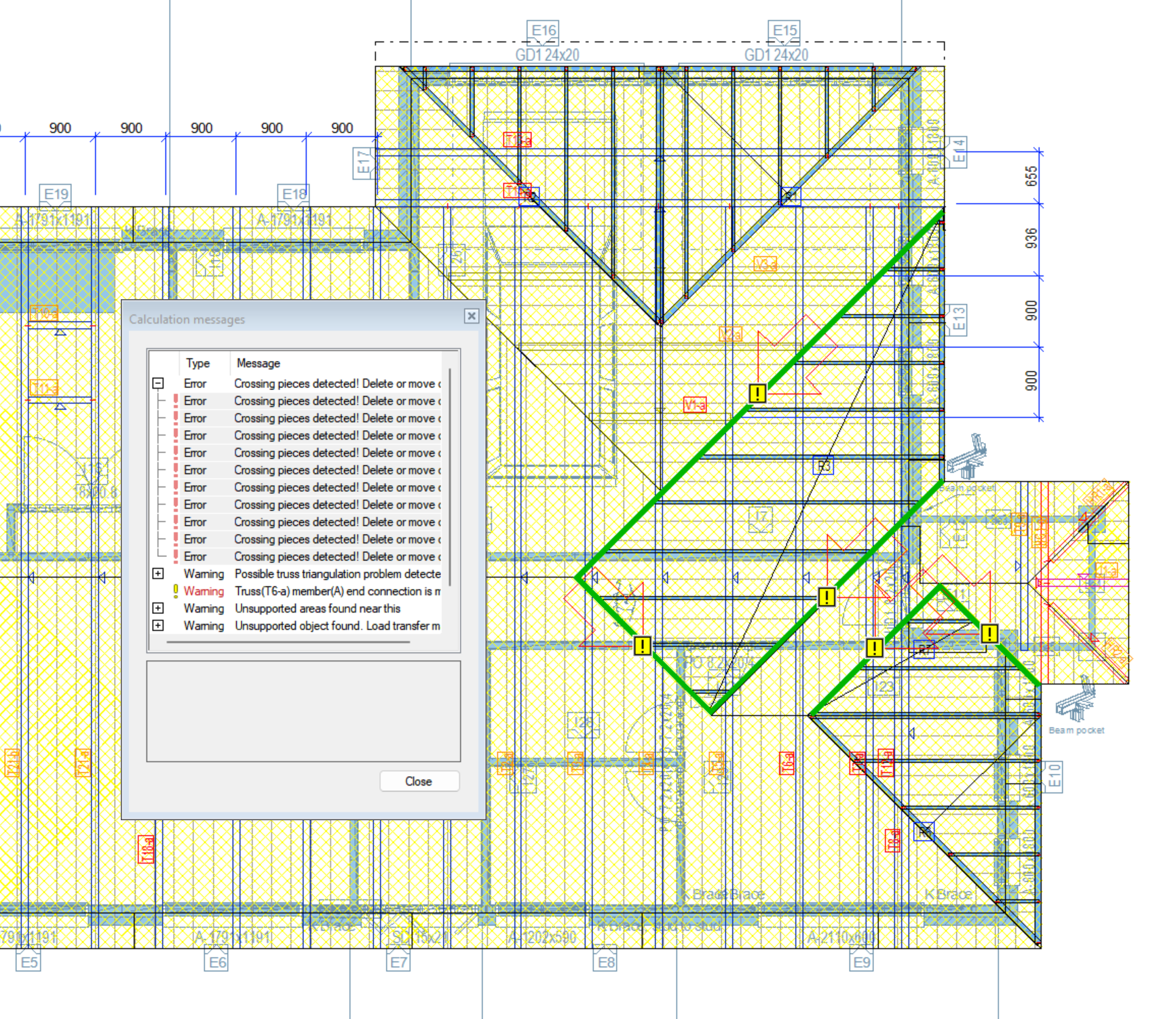
Crossing pieces detected! Delete or move one of the crossing pieces.
This error occurs when the the load path is unclear due to the pieces crossing with each other. If the error points at the roof panels, please make sure "Roof Panels" in truss enigneering setting is checked.
When "Roof Panels" is checked, FEA models of the roof panels would be generated in the background. Those models will be used to transfer loads.

Compression design error. Member buckles or design fails for other reason.
This error occurs when the effective length of the truss member exceeds the allowable defined by the slenderness raito in the building code. Please check that the member has sufficient restrain so that the effective length is shortened within range.
Vertical truss member missing at support location or at continuous bearing end.
It is compulsory that there is a web node or a vertical web at the location of support. Generally the truss generator can find the support locations and arrange the webs accordingly.
Truss without members detected.
This error occurs when the system does not detect any members in the trusses. Please generate parts for the trusses.
Member or structure supported by this object is not adequately supported! Please review your model!
This error occurs if the load coming from the structure above the truss is abonormal. Please check that the structure above is sufficiently supported.
