This page has the label SCROLL-HELP-CENTER-EXCLUDE-PAGE and it is not included in the published kben.vertex.fi site.
Switch between architectural and framing models
There are navigation buttons at the top of the working window that allow you to switch between drawing-model pairs. There is also a button that you can use to switch between the architectural and framing model.
Switch to the framing model (symbol of the architectural model is visible):
Switch to the architectural model

Text table
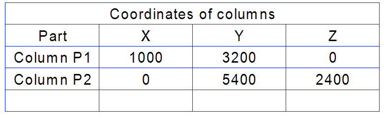
A table consists of rows and columns where you can add text. You can add the table to a drawing.
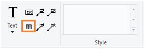
You can control the position of table texts in cells by aligning all texts left, right, or center. Cell width determines the amount of text that appears in a cell. The width of the table or its cells does not change with the length of the text. You can also change the position of the table in the drawing, and delete a row or column of a cell.
You can change cell widths by dragging, or you can point the width in the drawing. You can make the selected cells the same size, or fit the cells to their text content. You can clear texts from selected cells.
You can copy the text of the entire table to the clipboard and edit it in Excel. After editing, you can copy the text and paste it back into the open drawing.
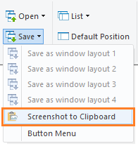
Screenshot to clipboard
Vertex also has a tool for taking a screenshot of the Vertex window to the clipboard. Of course, there are tools on the operating system side as well. The Vertex tool makes a screenshot of the graphics window even if there are other windows on the desktop.
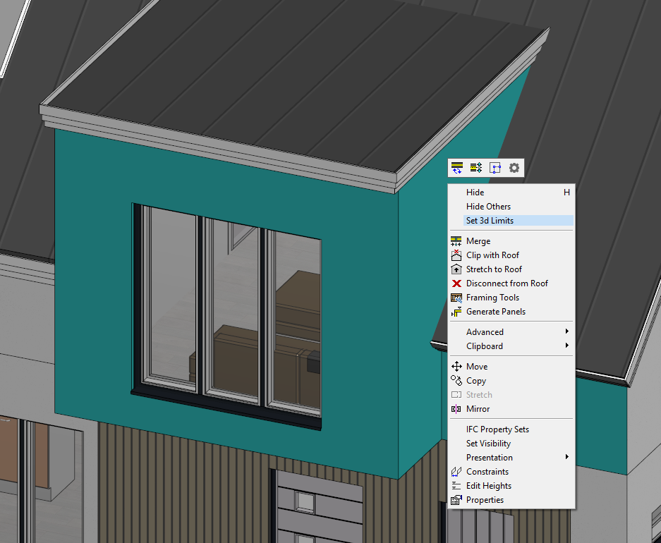
Set 3d limits with selected objects
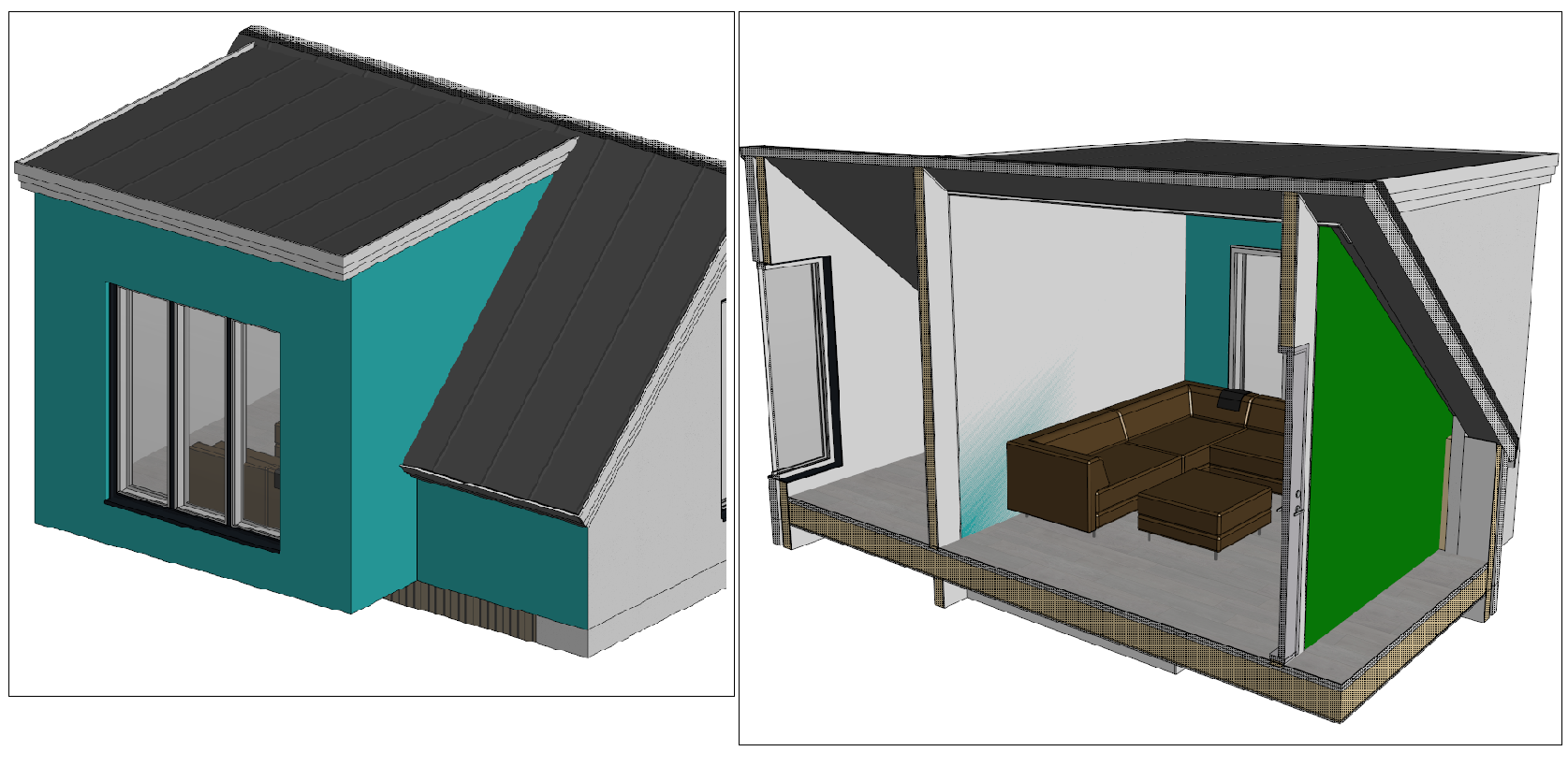
You can limit the 3D model by selecting the objects you want inside the limits. The limits are formed according to a slightly larger box that is added around the selected objects.
Model after settings the limits:
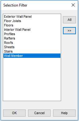
Selecting profiles by using profile properties as a filter
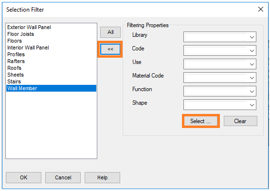
Select Wall Member in the Selection Filter:
Open the advanced properties with the arrow button to narrow the selection:
Use the Select function to select a bottom plate and clear the extra criteria. Just leave Use and/or Function, for example:
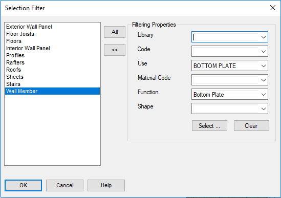
Close the dialog box by clicking OK.
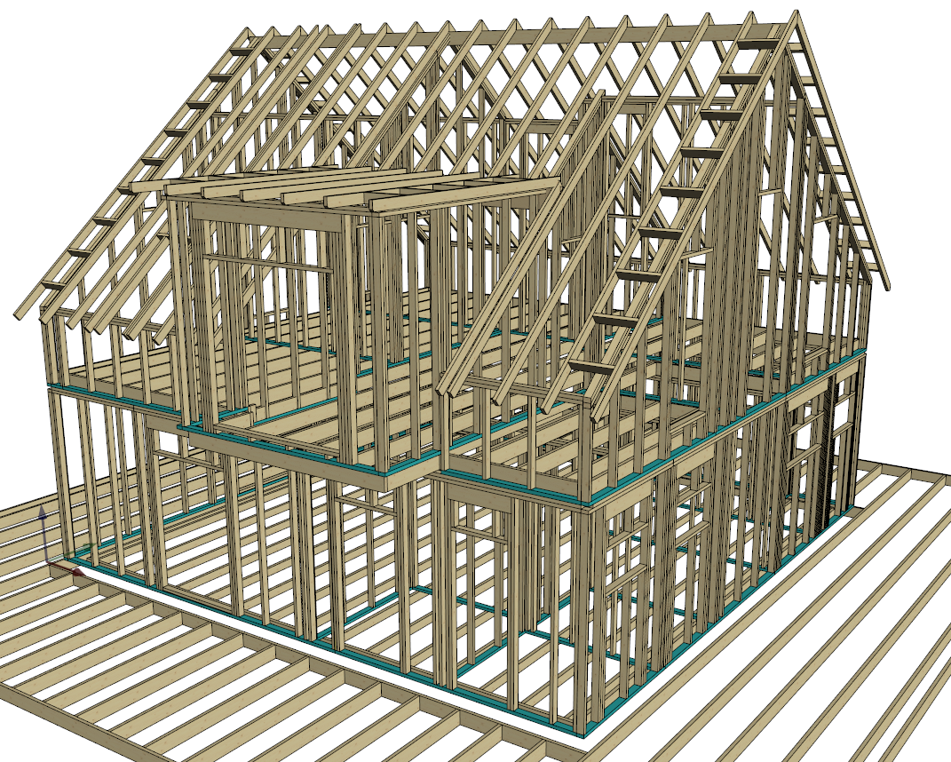
Press Ctrl+A to select all parts in the model → only the bottom plates will be selected.
Open drafting properties automatically when adding lines, dimensions, hatches or texts
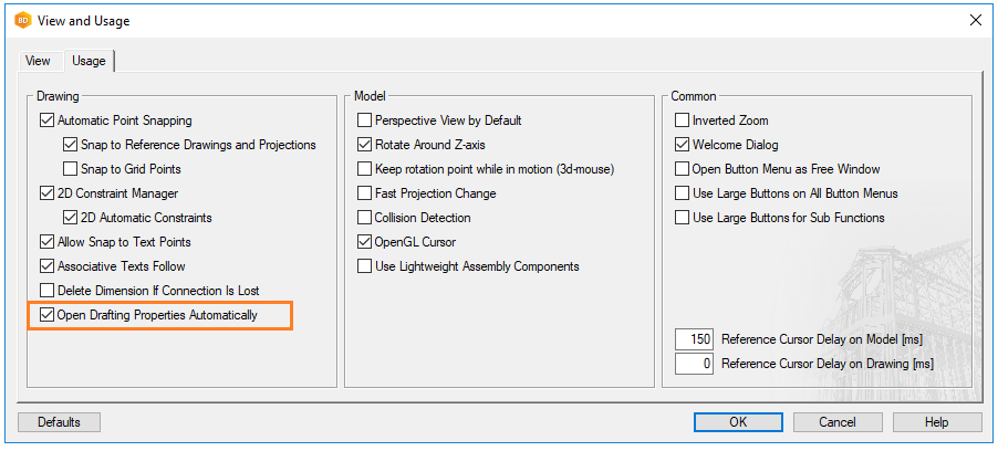
In preferences, you can configure that when you add basic 2D objects, the property parameters automatically open on the ribbon bar.
Select File→ Preferences → Drawings, models → Usage.
Release and unrelease window
When you have multiple screens, you can release the working window from the application and move it to another screen. Do either of the following:
-
Use the function on the tool strip
or select
View → Window → Arrange → Release/Unrelease Window
When you want to restore the working window to application, reselect the function.

External parts to panel drawing
You can connect an external object to a panel for displaying it in the panel drawing. The object can be, for example, a building component, a wall, a column, a beam, a G4 modeled part. Connecting an object does not affect the panel, but requires updating the panel drawing. If a panel drawing already exists, the program will suggest updating the drawing when you open the drawing.
-
Select the panel (wiht ALT key pressed), then the function Part Visibility.
Panel → Part Visibility

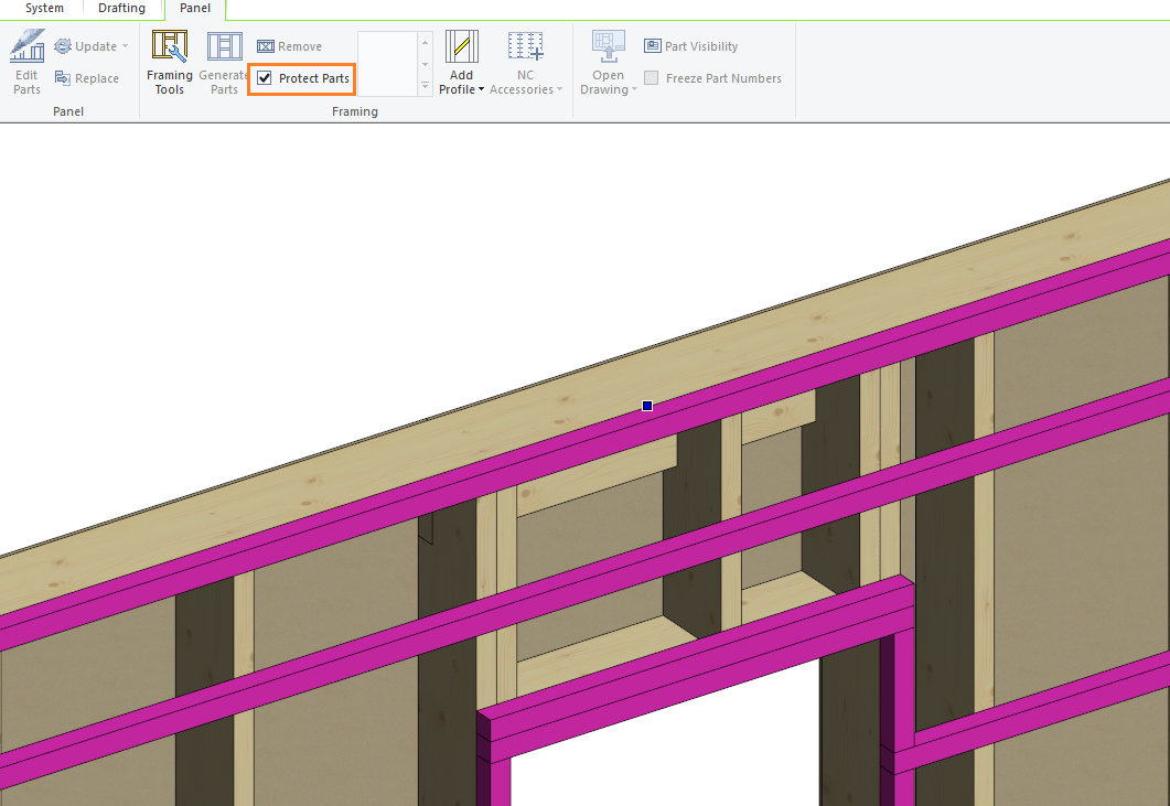
Protect parts
You can prevent regenerating the parts of a layer by protecting them.
-
Protecting parts in a layer does not prevent the editing or the removal of individual parts.
Tip: Select a panel with the ALT key pressed. Hold down the ALT key and click the desired layer → The layer in question is selected.
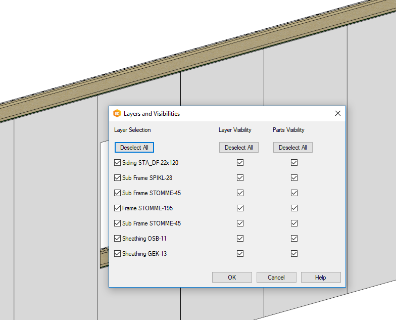
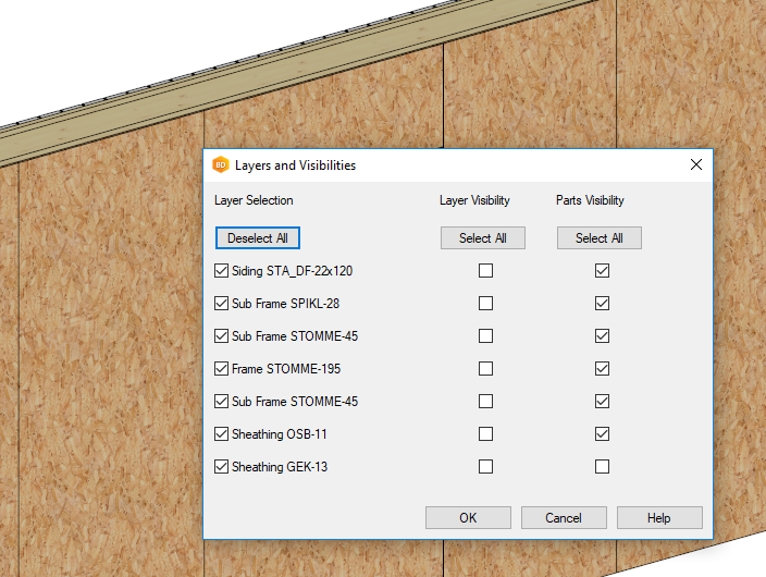
Layers and visibilities
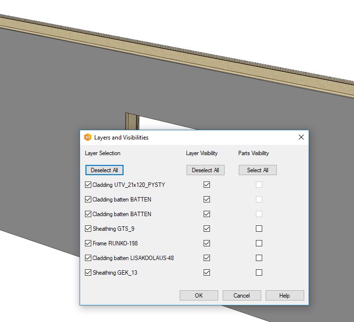
Manage the visibility of the layers and parts of a panel / panels.
-
Select the panel / panels with the ALT -key pressed → right-click → Layers and Visibility.
Tip: The selection remains until you make a new selection or press ESC.
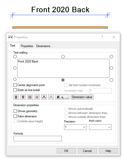
Add text to dimension
The dimension figure will still update.
-
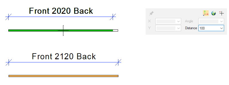
A dimension with text added to a profile.
Open project folder
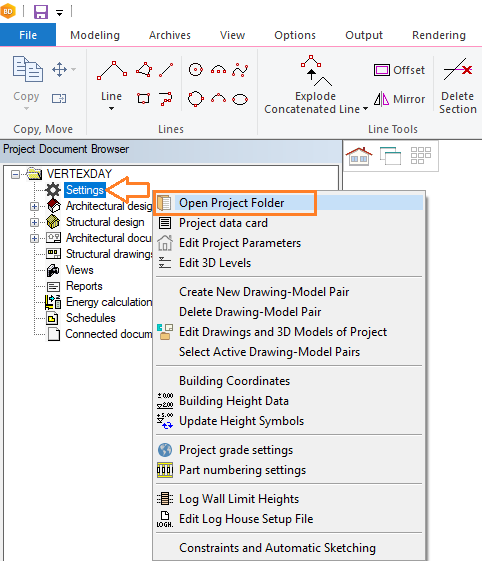
All the project files are saved in the project folder. You can view the location and contents of the project folder as follows:
-
Open project document browser.
-
Right-click Settings.
-
Select Open Project Folder.
This opens the File Explorer with an open project folder.
Open custom folder
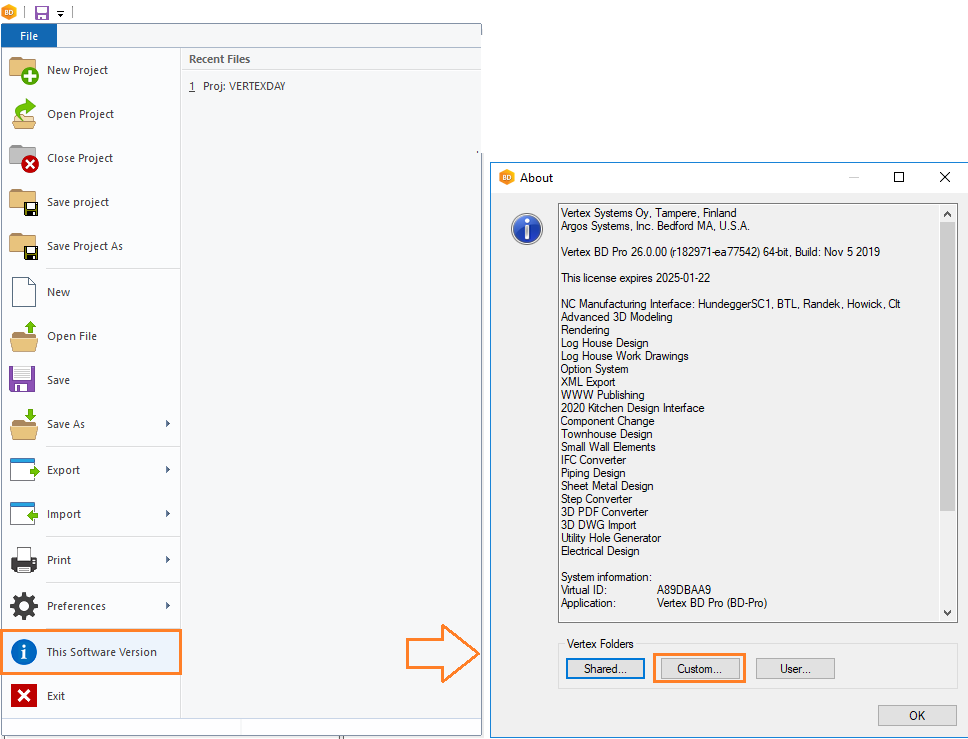
File → This Software Version
Quick filter
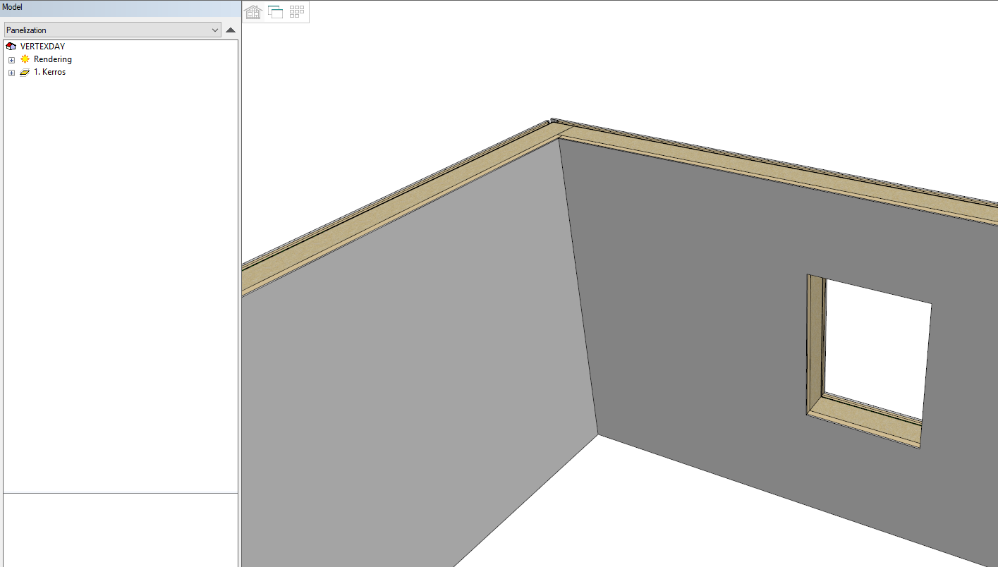
Quickly display the panel layers.
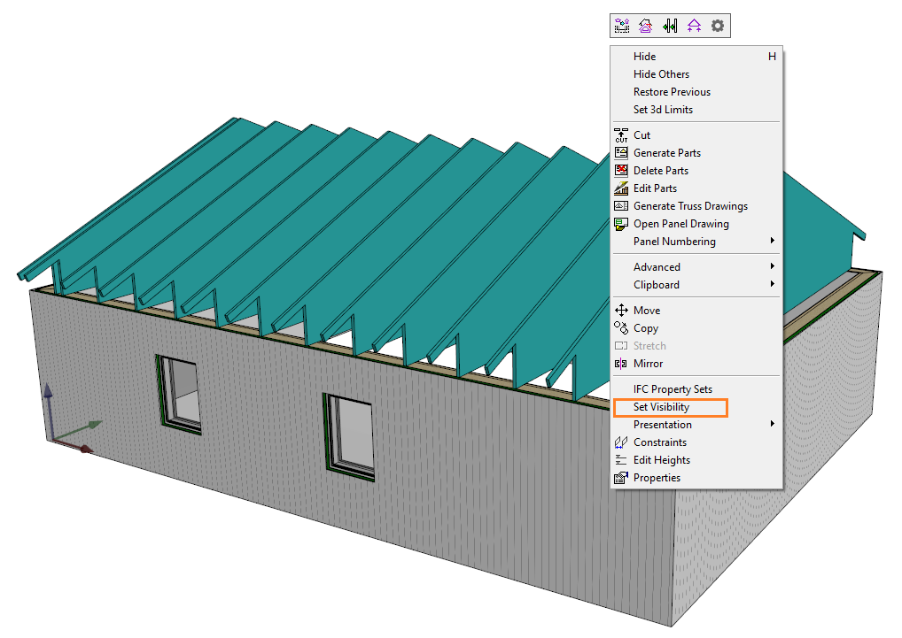
Set visibility
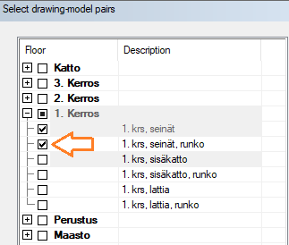
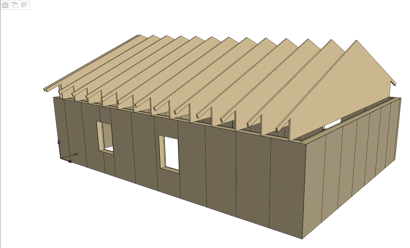
The visibility of trusses / beams in the architectural and framing drawing-model pairs.
-
No need to move from one drawing-model pair to another.
Select an object through surfaces (shortcut key W)
You can select an object through a surface in the model by pressing the W key. This is a one-off function, so you have to reselect it, if you want to select more objects through a surface.
As an example, trim a profile to a surface through another surface.
-
Select a profile. Select several profiles by holding down the Ctrl key.
-
Right-click to open the context-sensitive menu.
-
Select Trim to Plane.
-
Move the cursor over the surface, which you want to select through.
-
Press the W key. The program will make the nearest surface transparent. Keep pressing the W key until the desired surface is visible.
-
Click the surface.
TuplaVee.mp4 (video of using W key)
TarkistaEtäisyys.mp4 (video of using Verify Distance tool)
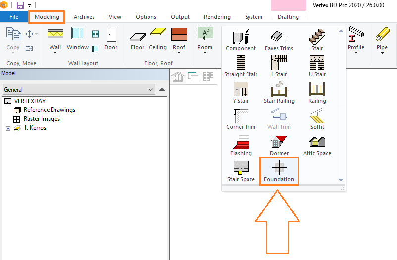
Add foundation columns
In 2D drawing → Modeling → Accessory Component.
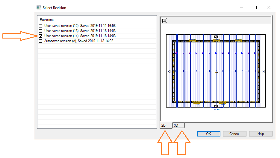
Select revision
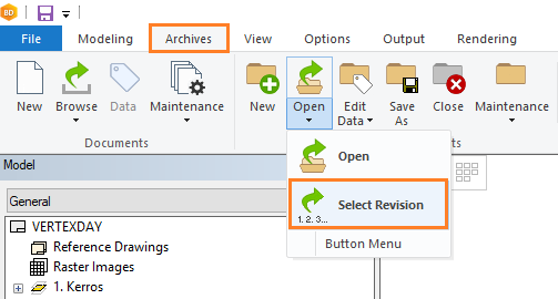
You can restore a previously saved version of an active project as follows:
Select Archives → Projects → Open → Select Revision.
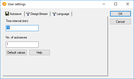
If you wish, you can increase the number of autosave versions.
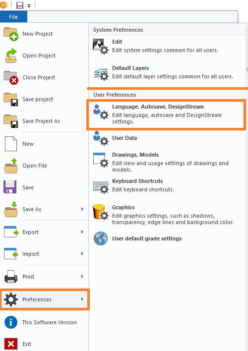
Number of autosavings (user-specific)
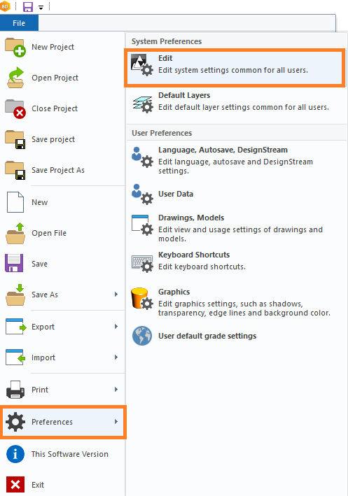
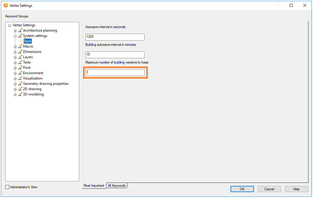
Maximum number of building versions to keep (common for all users)
Keep only latest revision of project
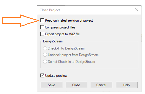
If you want to keep only the latest version of the project in the project folder, select Keep only latest version of project when you close the project.
The old project versions are then deleted from the project folder.