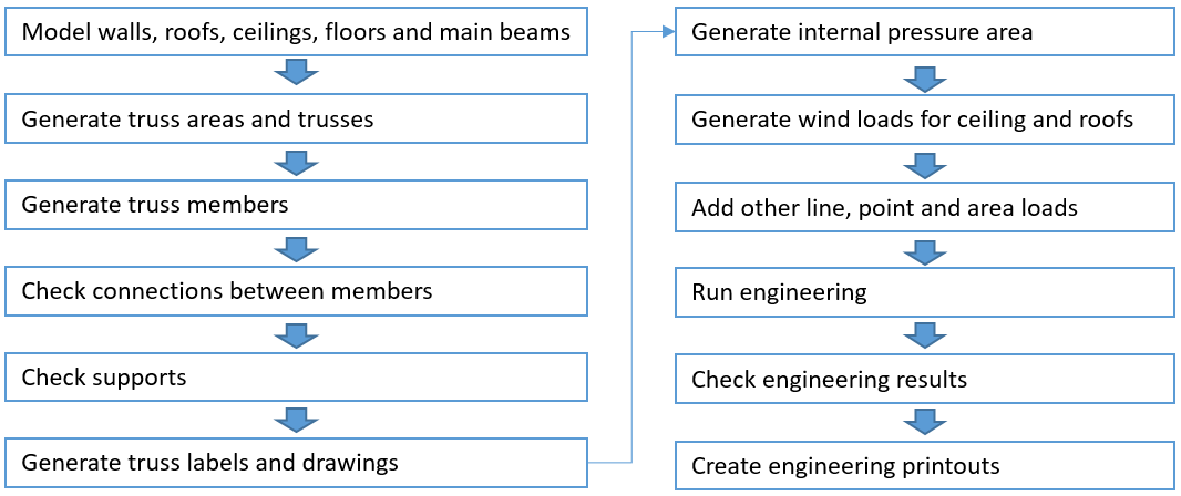
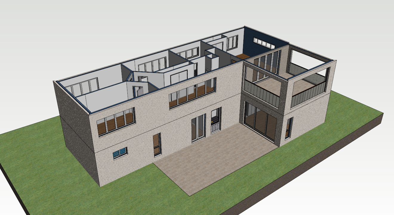
Step 1: Model walls, roofs, ceilings, floors and main beams
Trusses are supported by other objects in building model and the environment need to be completed before trusses are added. All objects are not working as bearing components. Walls, beams, roofs, ceilings and floors can work as bearing components with some limitation.
Checklist
-
Bearing attribute on walls is set on
-
Beam functionality is set to Main beam, beams should be supported by vertical bearing element, meaning column or bearing wall
-
Function property of the profiles which are transferring loads from covering material like sheeting to trusses must be "Rafters" or "Joists"
-
Profiles carrying loads from other members must be “Hip Rafters”, "Valley Rafters" or "Ridge Beams"
-
Physical contact or joint between members is needed to detect support relations and complete load transfer
-
"Rafters" should be supported by wall and hip rafter. No tolerance is allowed between end wall top and rafter. Adjust architectural wall height or hip slope height if needed
-
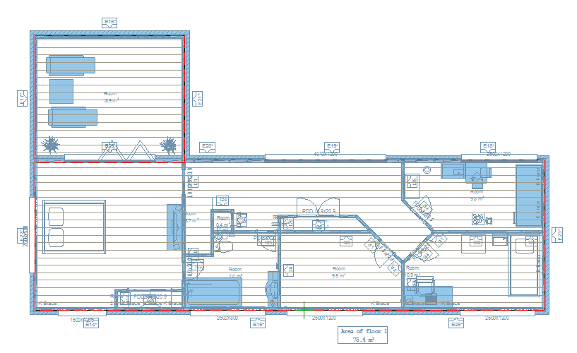
Don’t add loose walls into model, because outside of building they affect into solving of building dimensions for wind load generation
-
Use exterior walls only for building envelope not for interior walls, exterior wall chain should be closed that system can recognize building inside area for wind generation
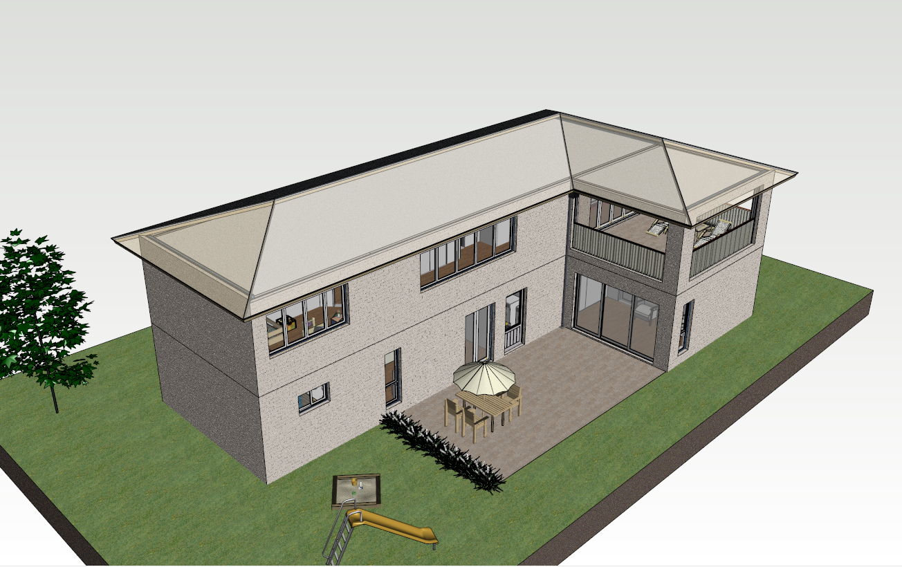
Step 2: Generate truss areas and trusses
Truss areas are generated by objects which are limiting the truss volume
Checklist
-
Height position of limiting objects, especially a hip slope should meet snug an end wall
-
Connections between trusses, jack trusses perpendicular to girder truss should meet girder
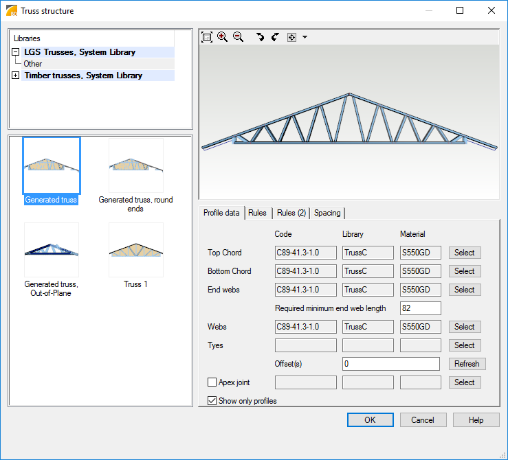
Step 3: Generate truss members
Truss members are generated using rules defined by user.
Checklist
-
Check member parameters and truss type
-
Check member material, selected grade is used in engineering
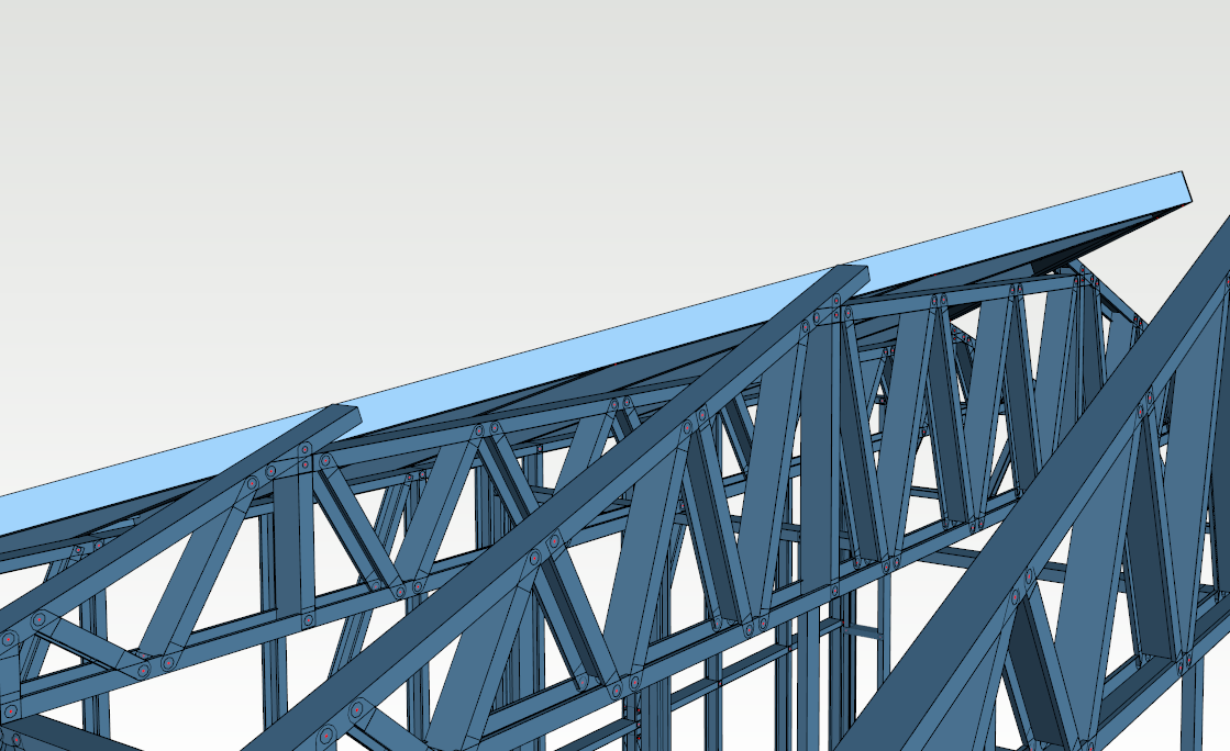
Step 4: Check connections between members
Connections must be defined between truss members. Truss member framing is adding connections between members but manually inserted members must be checked by user.
Checklist
-
Check used fastener types and codes, capacity of connection is based on fastener type and code
-
Trimming connection only between truss members can be used but then connection is not engineered
-
If program is configured to force web connection at bearing location then saddle truss verticals should be in line with top chord of truss below or at least middle of red fastener pattern macro in connection should be between top chord faces below
-
Use joist hangers or direct screw connection between trusses to generate support relation between girder truss and trusses supported by girder
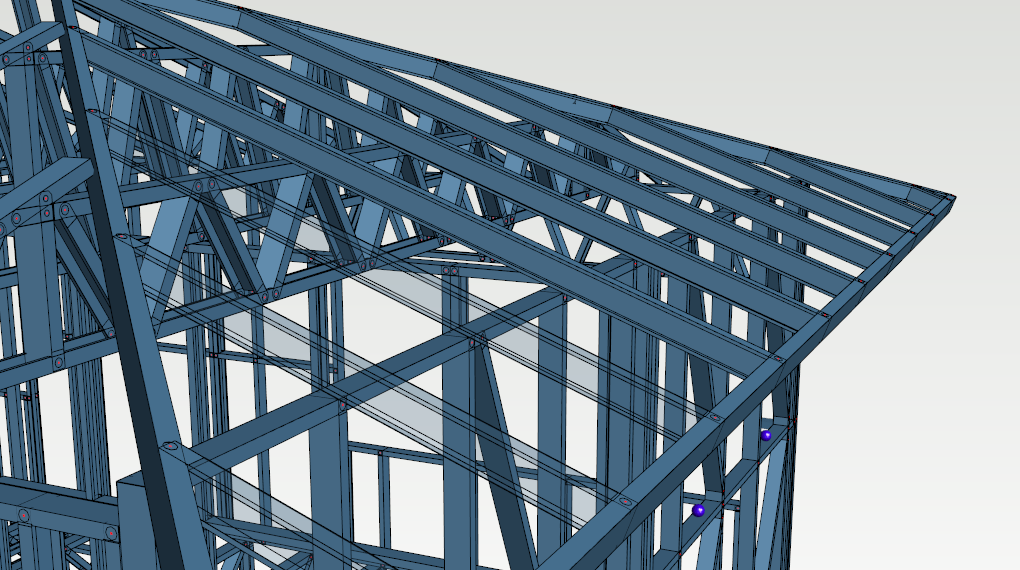
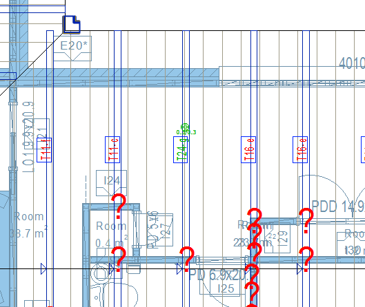
Step 5: Check supports
There has to be physical contact or connection between supported and supporting objects. Trusses which are supported by another trusses need to be connected by user.
Checklist
-
Check truss to truss supports and add connections
-
Check bearing wall heights and contacts with truss members
-
Check bearing main beam positions and contacts with truss members
-
Hip drop truss/girder sloping top chords should not extend inside hip rafter, otherwise bad support relation is found during engineering
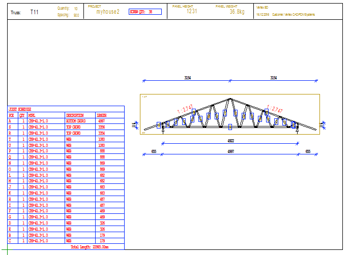
Step 6: Generate truss labels and drawings
Truss and truss member labels are created with truss drawing. Truss drawing must be created and updated before Truss Design. Labels are used to refer to engineering results.
Checklist
-
Create truss drawings before Truss Design
-
Update truss drawings if truss geometry is changed
Step 7: Generate internal pressure area
Internal pressure area is space inside building limited by exterior walls and interior ceiling or roof. If ceiling is permeable then roof is limiting internal pressure area.
Checklist
-
Check generated closed poly line to limit internal pressure areas and adjust poly line if needed
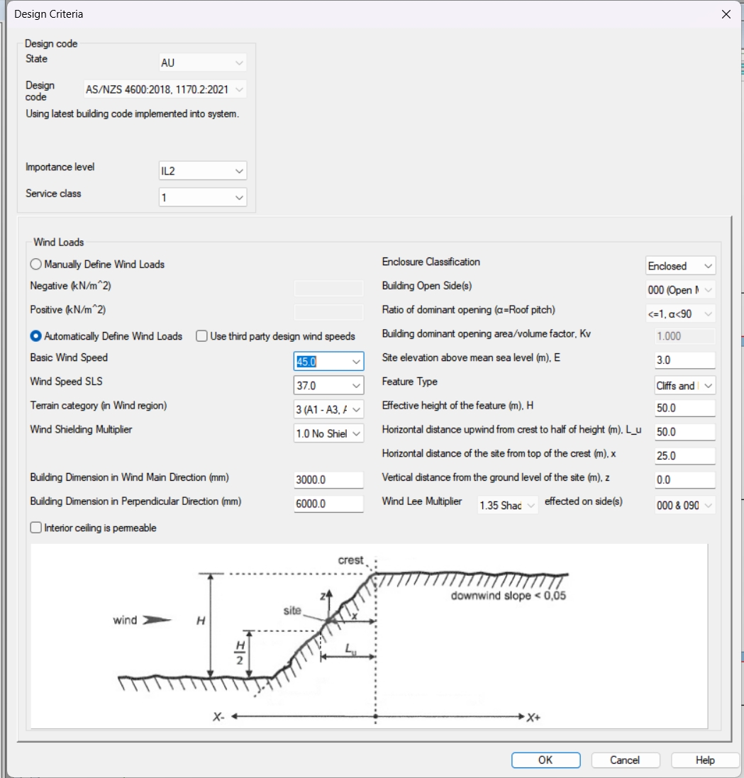
Step 8: Generate wind loads for ceiling and roofs
Wind loads are generated according to the selected building code.
Checklist
-
Select main wind direction during input based on building site topology and environmental aspects
-
Check Design Criteria defaults, especially building location compared to terrain topology
-
Check meaning of exposure and enclosure parameters from building code
-
User can also use manual defined wind loads if those are specified by the engineer.
-
User can insert design wind speeds if those are specified by the engineer.
Step 9: Add other line, point and area loads
Point, line or area loads can be modeled manually. All loads should be modeled into same drawing-model pair where bearing object is. To apply point or line load to bottom chord, apply load first to ceiling and then move it to contact with bottom chord.
Checklist
-
Correct drawing-model pair
-
Check that point and line loads are applied to truss members not to trusses
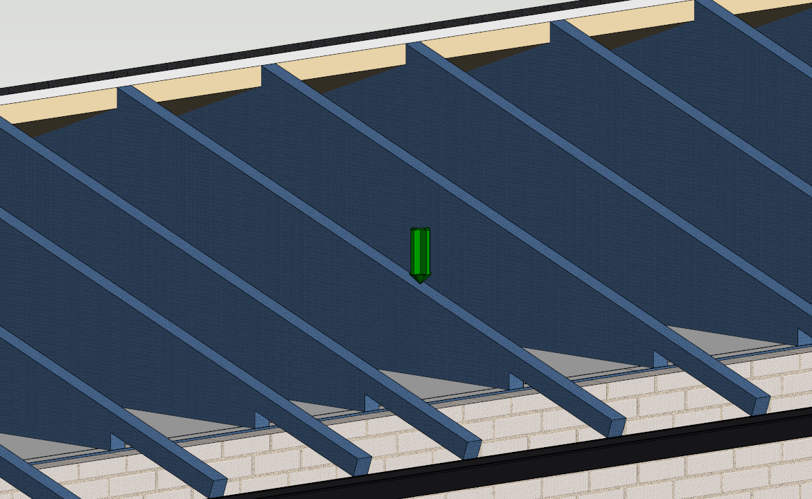
Step 10: Run engineering
Engineering can be done for one or multiple trusses or rafters. Passed truss after engineering is indicated in green color label. Engineering label is added into end of truss label.
Checklist
-
Check generate errors and warnings, they guide you to make changes into your building model
-
Connection model checker can be used to notify missing support relations
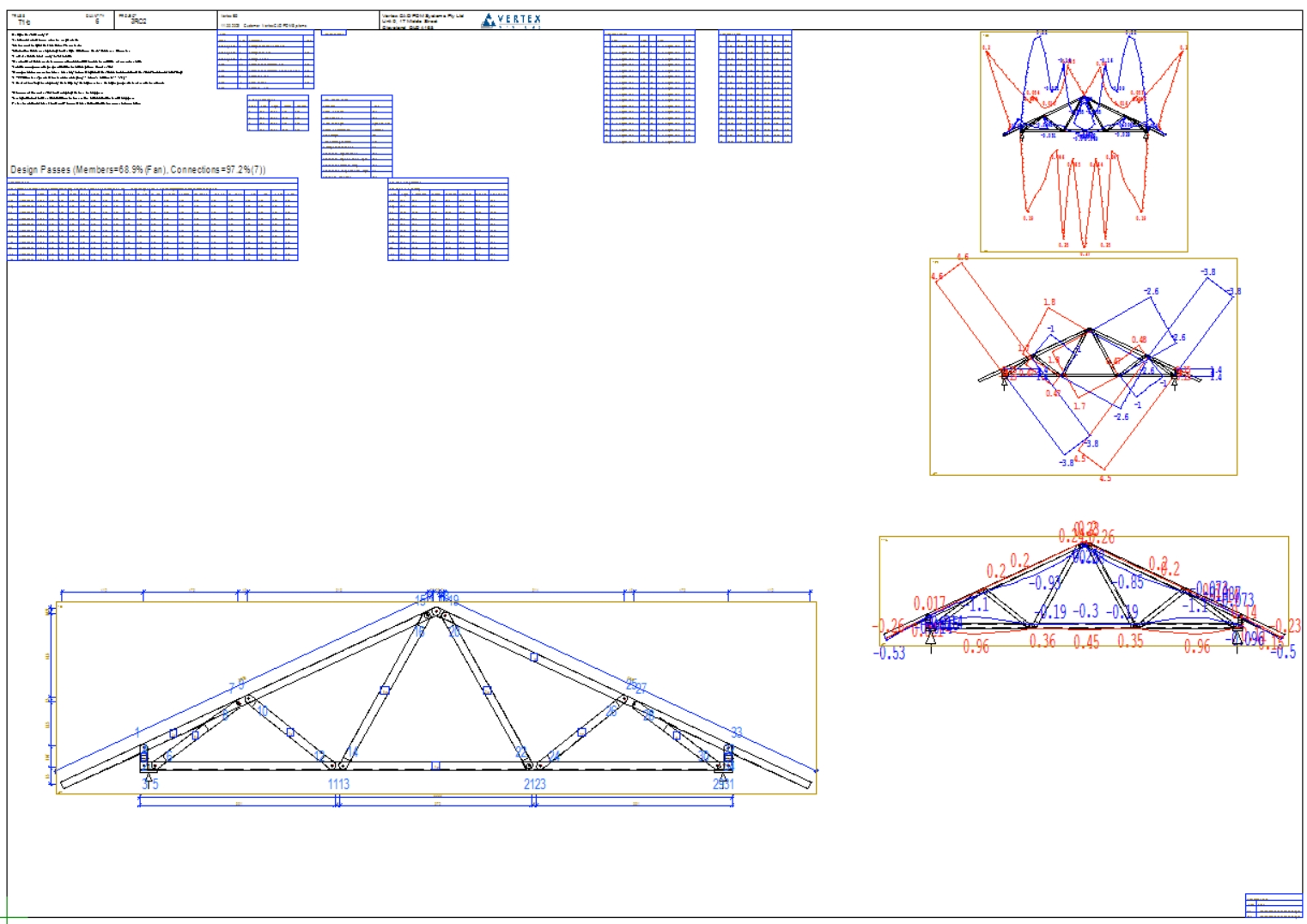
Step 11: Check engineering results
Results can be opened in 3d model or 2d drawing. Drawing shows stress indices for each member. If the stress index is over 1.0 then capacity of member is exceeded.
What to do if the design fails
-
Decrease truss spacing
-
Increase the number of the diagonal members
-
Use boxed truss structures for the critical parts
-
Use ply trusses
-
Check load path
Step 12: Create engineering printouts
Engineering results are shown in printouts.
Checklist
-
Check that presented supports are in correct locations
-
Check moment and axial force diagrams