
You can import a 3D model into Vertex BD from any architectural CAD software using the IFC file format. For example Autodesk Revit® can export model as an IFC file. The Industry Foundation Classes (IFC) data model is intended to describe building and construction industry data. IFC is a platform neutral, open file format specification that is not controlled by a single vendor or group of vendors. You can import an IFC model either as a reference model (used for creating new macros, to show trusses modeled in other software, for example, etc..) or as an object model to be framed using the Vertex framing tools.
For any IFC model, it is recommended you open it first in an IFC viewer or editor to review the content and setup of the IFC file. Example free viewer is Solibri Anywhere or BIMvision.
-
Download example.ifc.
-
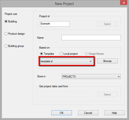
Create a new project. Click File -> New project. Type in a name in the Project id field and select a parametric (3D-levels) template. Click OK.
Make sure you select a template that supports 3D-Levels functionality. The template name may be different on your Vertex BD version, for example TEMPL-ZL or TEMPL-PARAMETRIC.
-
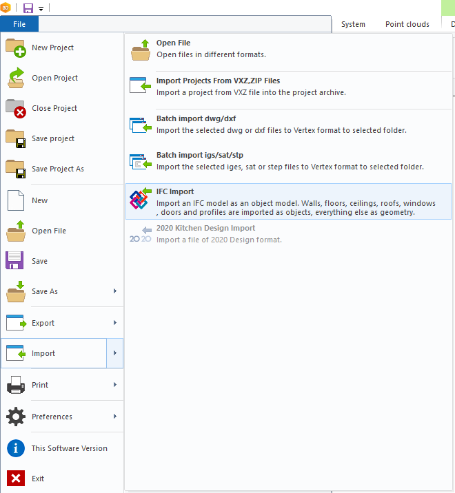
Select File -> Import -> IFC Import.
-
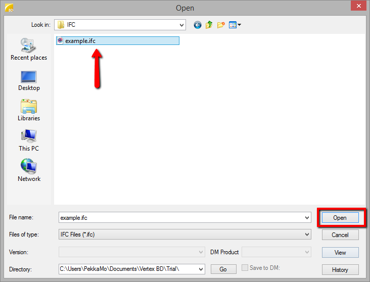
Select the IFC file from your hard drive.
-
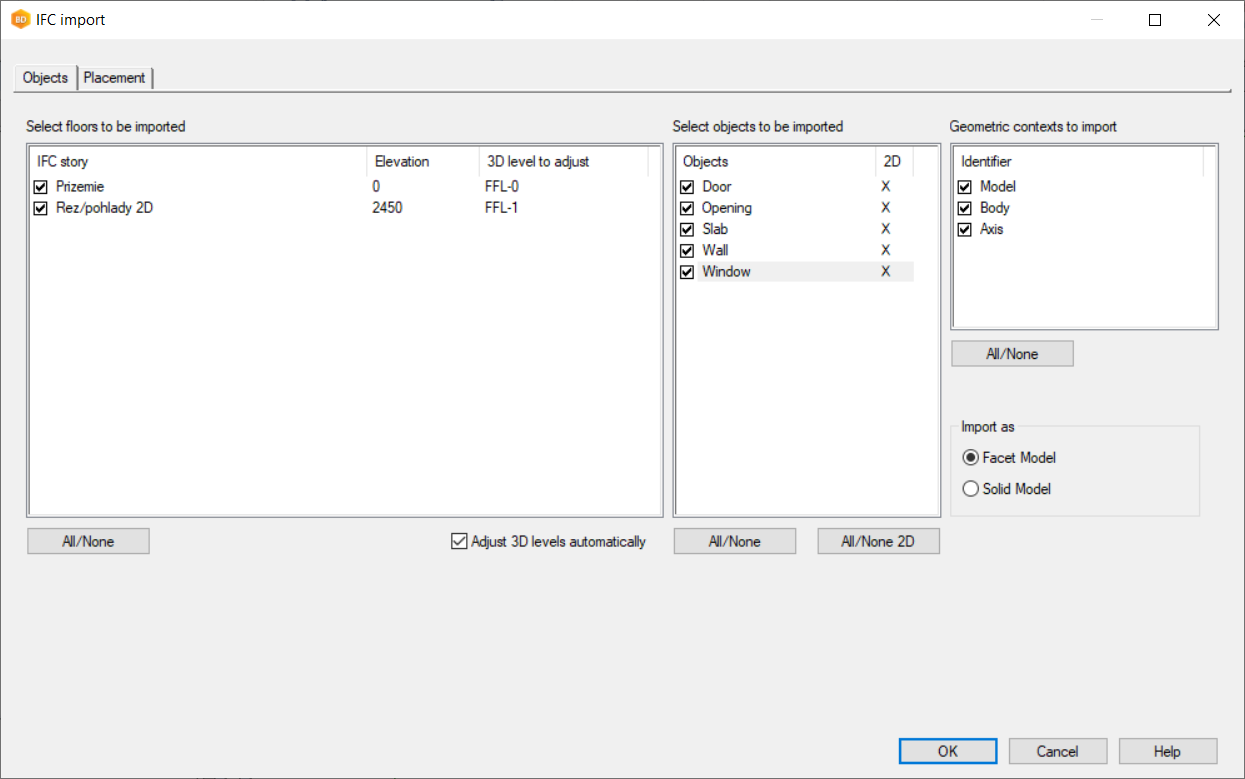
Select the levels and object types you want to import into Vertex BD. Also, you can check the "Adjust 3D levels automatically" checkbox, then select a 3D level for each level detected in the IFC file. This controls which drawing-model pair the objects will be placed in during the conversion.
You can control by object type if 2D geometry is created or not for imported IFC object. Doors, Openings, Slabs, Walls and Windows are recommended to be shown in 2d. Additional objects can be shown but the more visible in 2D the longer the import process takes.
Choose Facet Model if you do not care about true surfaces of curved objects, for example pipes (lighter model).
Choose Solid Model if you want to see true curves of objects (heavier model).
-
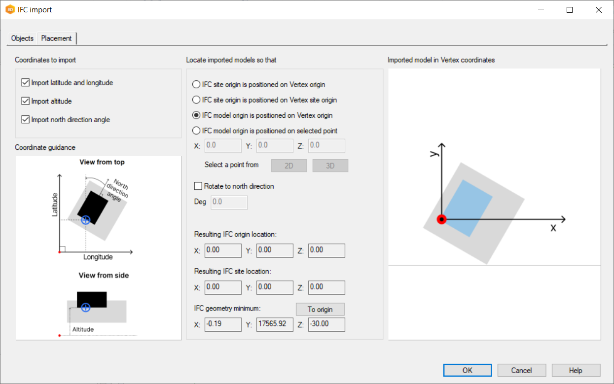
On the Placement page choose to locate the imported model so that IFC model origin is positioned on Vertex origin
-
Press OK and import the model.
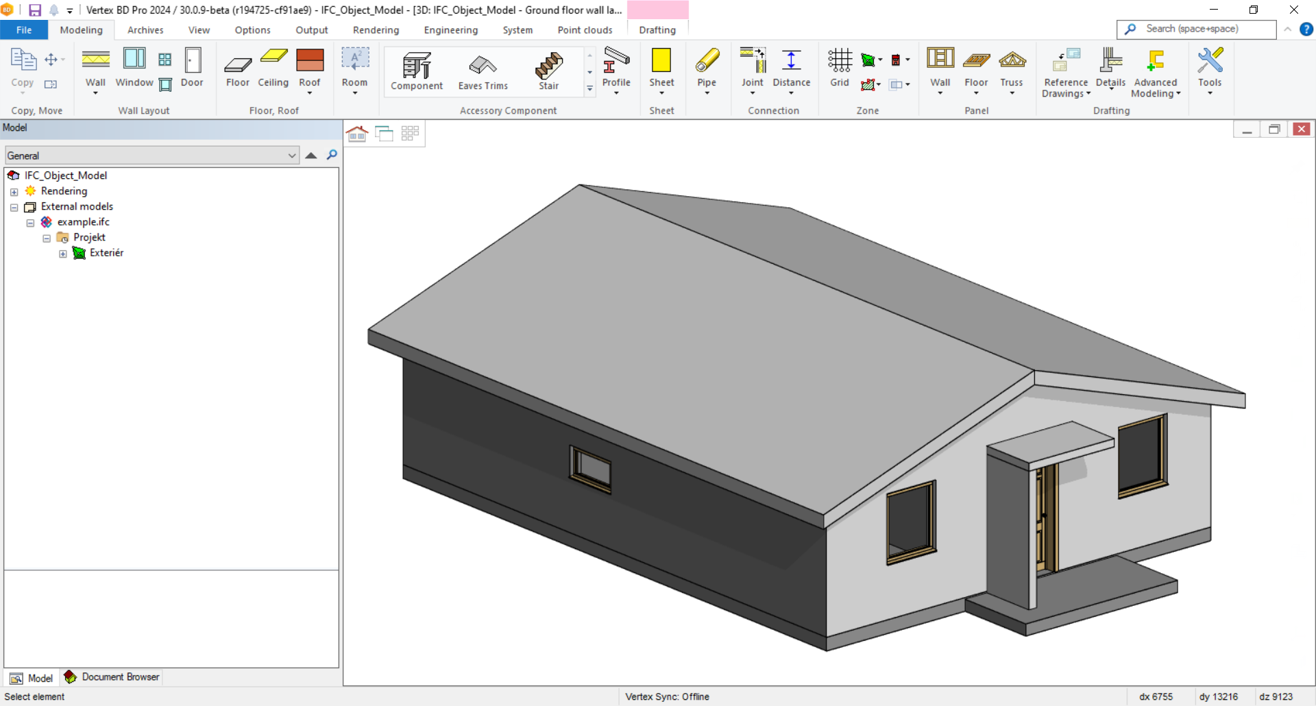
After the import is complete, all objects are IFC objects and you can start part conversion, if needed.
-
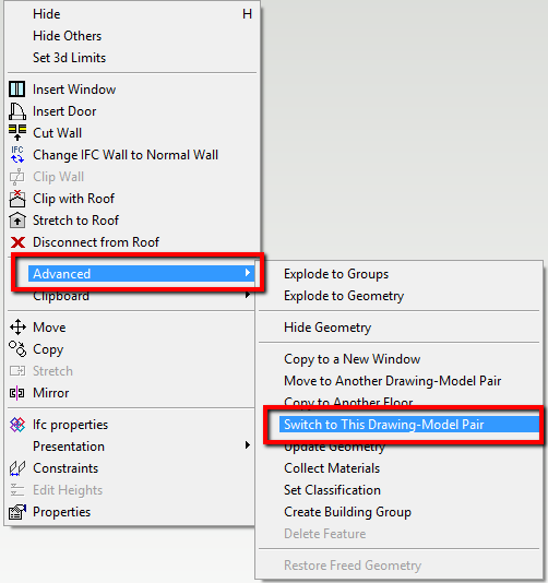
Switch to a drawing-model pair where your walls are. Select a wall in 3D model, right-click, choose Advanced –> Switch to this drawing model pair.
-
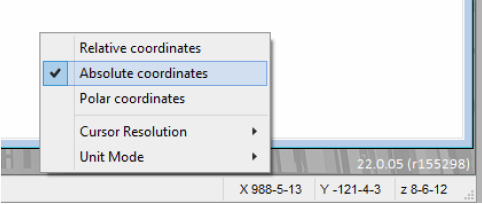
Switch to 2D view (press F2 key) and right-click and select Zoom Extents. If the layout seems to be far away from the green origin marker, you should move the whole building model close to the origin. To find out how far away the layout is from the origin, right-click on the coordinate number on the bottom right corner and select Absolute coordinates.
Move your mouse cursor close to bottom-left corner of your layout to see the coordinate values. If the X or Y value is greater than 1000 feet (300 meters), then you should move the building model closer to the origin.
-
Additional clean up will most likely be required before generating the framing. For example, the architectural model may have extra wall splices that you may want to merge together. Walls may also have been modelled as very tall walls that you will need to separate into each level of the building (depending on how you want it to be framed).