
Insulation
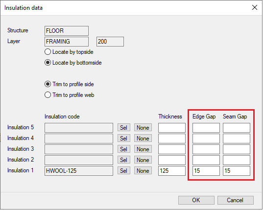
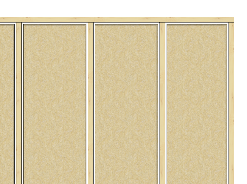
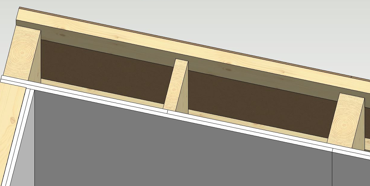
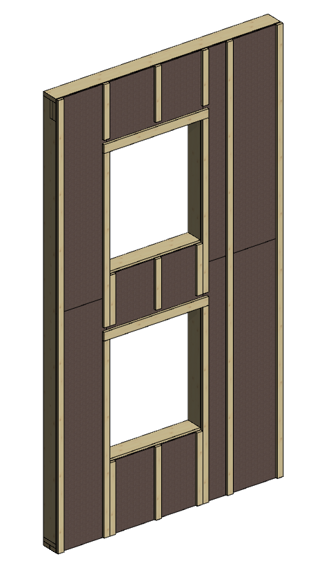
Add insulation to structure with a gap
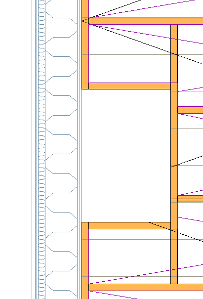
The distance between the insulation and the profiles and between the two insulation boards is defined by different values. The installation gap is especially needed in the installation of hard insulation boards, when space is left for the extruded insulation compound.
Framing tools
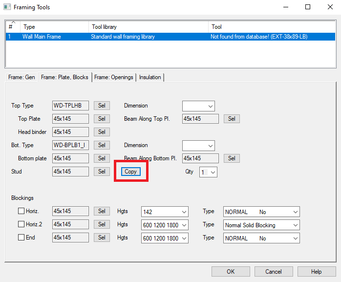
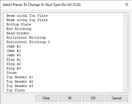
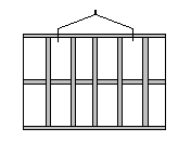
Copy profile code to all fields
There is now a button to easily assign the same profile code to multiple fields in the wall framing tool. Previously this was available in the Imperial versions only. The layout of the framing tools has also been improved
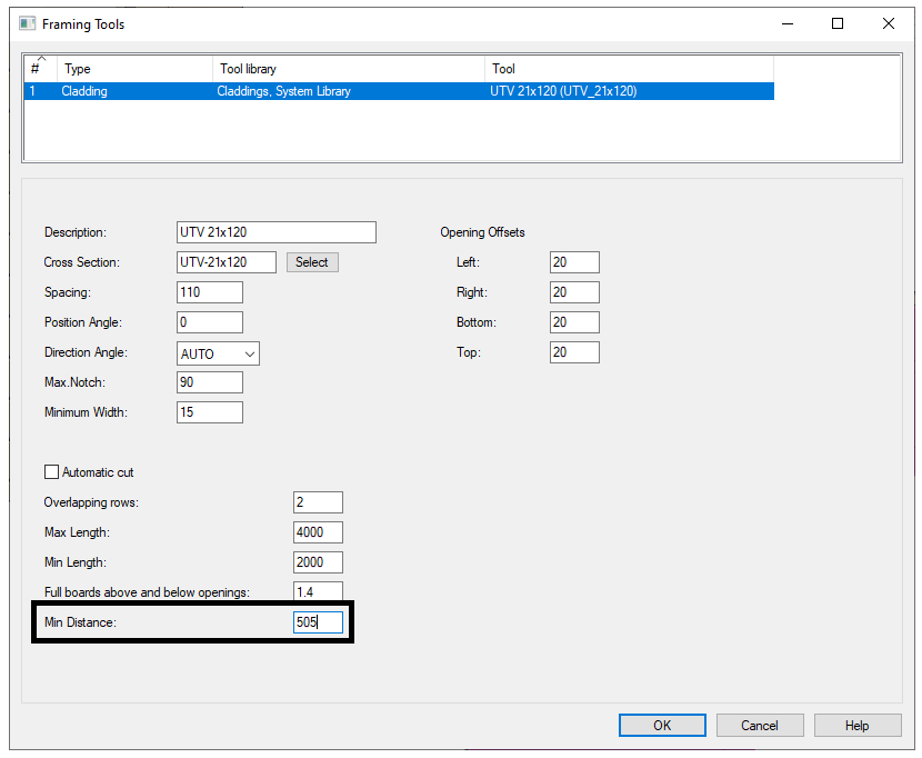
Sheet seam placing improvement with wide extra studs
It is possible to set a minimum distance from seam to the edge of the stud. This can be set in detail-file (eg. wd.xx), for example:
sheet_seam_stud_min_edge_dist = 22
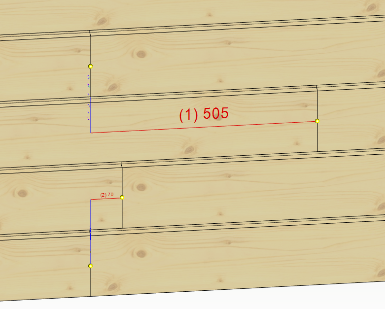
Now sheet edge is assumed to be on the stud if it "overlaps" studs enough.
If sheet_seam_stud_min_edge_dist is not given or its value < 0, then system works as before.
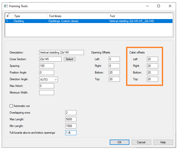
Control added for cladding board cut offsets
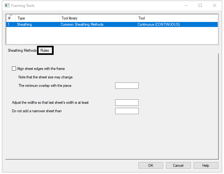
Sheathing optimization
New fields to sheeting tools databases:
SHT_ALIGN A1
SHT_ADJ_LIM A80
SHT_MIN_E_DIST A80
SHT_ALIGN = 1/0, alignment of the joints of the plates, if on, then all the seams will be aligned with the frame, if necessary, the size of the plate will also be changed within the plate area
SHT_ADJ_LIM = measure that narrower plates are made wider by narrowing the adjacent plate. Note! If the width is less than SHEET_MIN_W, then the widths are not changed but the disc is removed.
SHT_MIN_E_DIST = minimum distance from the edge of the sheet to the edge of the profile. Default value is 22mm.
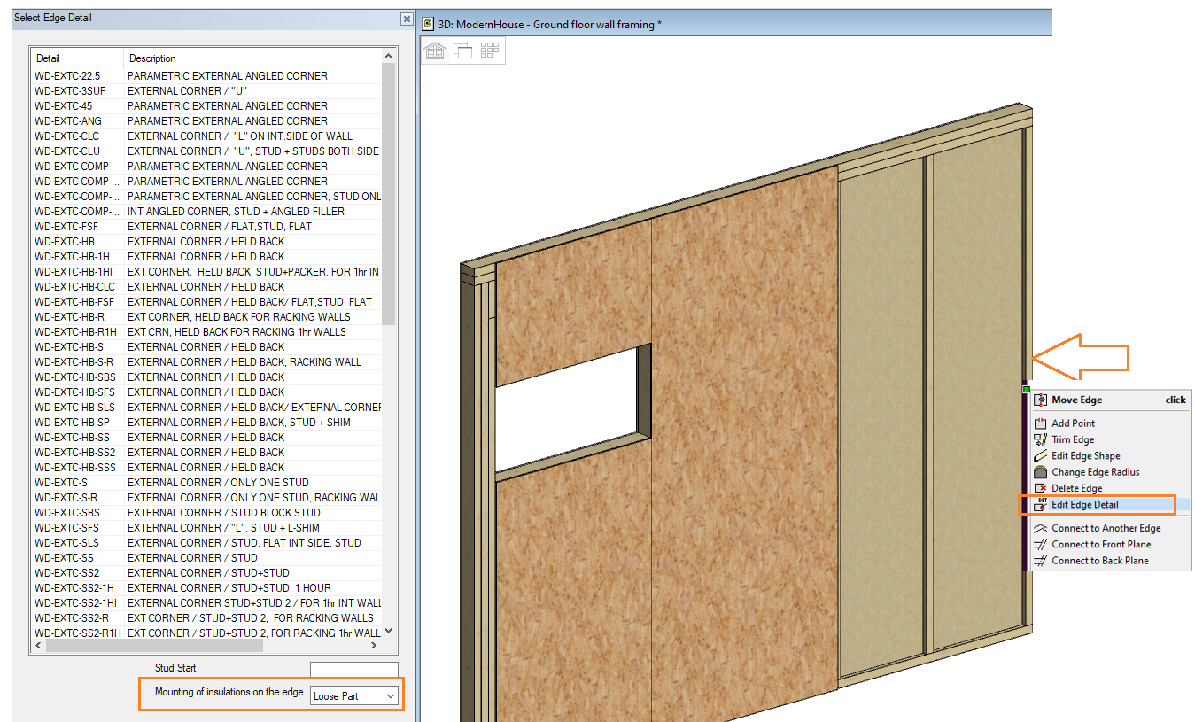
Insulation at the corner (last insulation/stud bay) to be loose part (in main frame and sub frame)
Horizontal framing tools
Possibility to have sheets automatically in details added to horizontal structure

New style to add battens around the openings
Cutting of trimmers:
-
Set Length = LONG (1) and Cut Mode = TOP in new Length-page for the part in framing details
Adjust how parts are trimmed to an opening header:
-
Add PieceA end = LOWER to joint between JST and OHDRT with offset -45.
-
Add PieceA end = UPPER to joint between JST and OHDRT without offset
Add cripples only below the opening:
-
Use detail CRIPPLE_BOT instead of CRIPPLE in detail-file.
Siding offsets around an electrical cabinet
Siding offsets are always the same for every opening in the wall.
You can define own offsets for electrical cabinets.
New fields can now be supported:
ELCABTOL_LEFT
ELCABTOL_RIGHT
ELCABTOL_BOTTOM
ELCABTOL_TOP
Note: Ask for more information from customer service
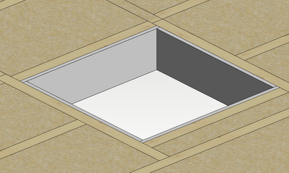
Ceiling/floor holes to be done so that hole header goes to next available joist
Default detail for header edge lines that have moved inwards, can be defined in details-file:
default= HEADER_CUTOUT OP_HEADER
Default opening detail for side edge line can be defined in details-file:
default= SIDE_CUTOUT OP_TRIMMER
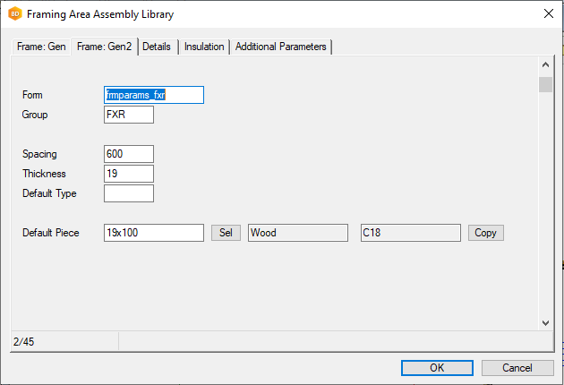
Floor and Roof Framing Libraries have been improved
The Floor and roof framing library has been improved so it is similar to that of the wall framing tool library. The old table-based layout is gone and it is now user friendly and clear how the settings can be used
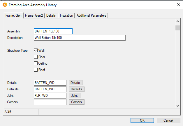
Floor and Roof Framing Libraries have been improved (continued).
It is also now easy to change default profiles, library and material, just click the Copy button for the default piece and it will check the additional parameters for codes that can be changed. Previously you had to take care when changing the additional parameters manually
Lifting points for Wall Panels
Add lifting holes to the top plate (all environments)
Under Wall panels → Framing accessories → lifting points you can now easily add lifting holes to all panels taking into account the centre of gravity and weight of the panels in 1, 2 or 4 hole configurations.
Lifting points with a Rectangular Hollow Section (Light Gauge Steel only)
Easily turn a stud into a lifting point for a module by clicking it in the layout plan or 3d model. The original stud is deleted and replaced with a rectangular hollow section with new studs on each side. A service hole is added to the top track and a hollow section. The tool can be customized to add additional holes as required
