Modeling Supports for Trusses
Supports and Bearers
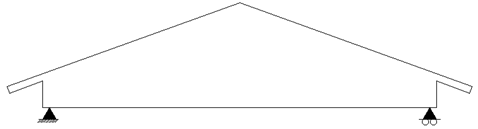
Truss supports suppose to be either the pin or roller supports. Automatic pinned support is added to the lowest part of truss on left hand side from viewing direction. All the rest supports are roller ones.
Viewing direction can be changed using function “Set Truss View Direction” in “Advanced menu” of truss.
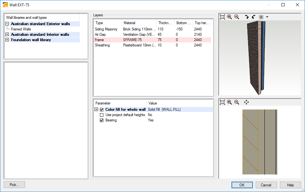
Use ordinary Vertex BD modeling tools to define bearing walls and primary beams. Usually exterior walls and foundation walls are defined to be load bearing by default, but user can switch this behavior on or off using wall properties dialog. Interior walls are most often defined as non-bearing by default in Vertex BD environment.
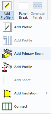
Beams added using Add Profile function are non-bearing, but beams added using Add primary beam function are load bearing. Select first the area object (i.e. ceiling) where the primary beam will be located and then select Add Profile > Add Primary Beam.
Columns are load bearing by default.
Support relations between objects
Vertex BD engineering bearing rule is that a passing object is bearing an ending object. If two connected objects are ending in the same point, crossing pieces error is generated during engineering.
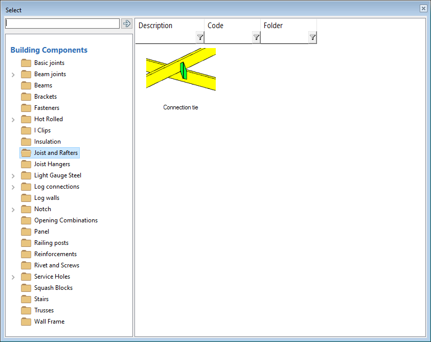
Default rule of primary and secondary members can be turned the other way round by adding a Connection Tie between members.
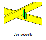
Connection tie input is asking a user to define "Primary beam" and "Secondary beam". Primary beam is carrying secondary beam, but not vice versa. Bearing relation can be changed by choosing the beams in opposite order.
Modeling Trusses
Use ordinary Vertex BD modeling tools to define truss areas and truss shapes. Before defining truss areas user has to model ceilings and roofs. Ceiling areas and roof slopes are also used to distribute acting uniform loads to load bearing members.
When truss shapes are defined, modify truss shapes giving tolerances and offsets that are required for connectors or rafters.
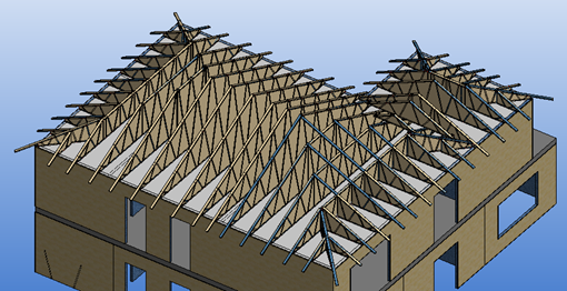
Hip roofs and load transfer
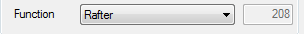
Rafters are often transferring loads from roof to truss. Typical case is hip end and drop down to leave space for rafters. When using framing tools, typically those profile types are correct. If user is adding single profiles manually, profile types must be checked. Load transfer requires some specific types of members. Profile types to use are as follows:
-
Profiles transferring load must be “Rafters” or “Joists” (load transfer from other members is not allowed)

-
Profiles carrying loads from other members must be “Hip Rafters”

Valley trusses and support
If there is short valley trusses and extra support is needed between trusses to carry loads, profile type must be “Main Beam”. Construction should be made as it is, if proper cutting lengths and profile feature are needed for production. If bearing member is made only to create support for truss engineering, easiest way to make a support add parallel support below the valley truss.

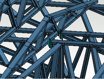
Valley/saddle truss vertical web members
First time when valley truss members are generated, web verticals are not generated to main truss locations, because bearings are not recognized and valley truss can slide along main truss.
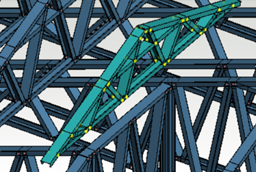
After member generation user can add connection tie joints between main truss and valley truss and after that regenerate valley truss members.
Now bearings are recognized and vertical web members are generated.
Physical Contact or Joints are Required
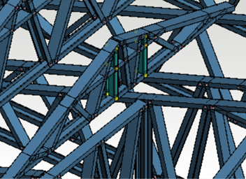
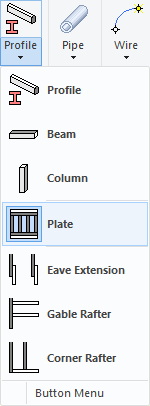
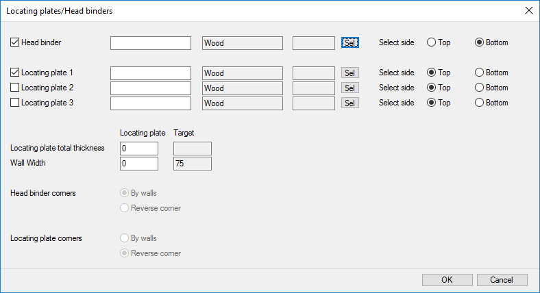
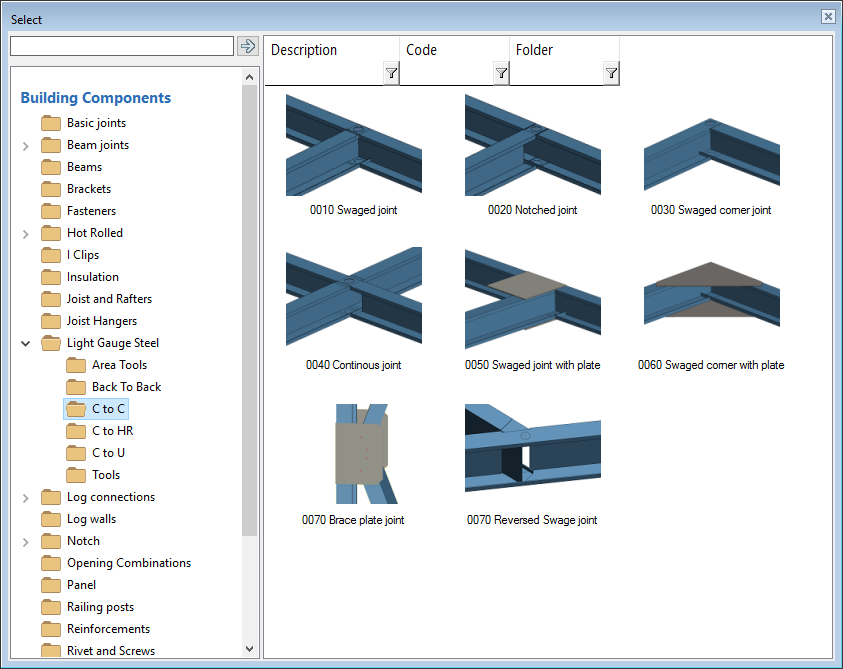
Physical contact or joint between objects is required for support condition between truss member and other bearing object. Contact should cover the total width of supported member otherwise the contact is not working as load transferring contact. If there is space between top of the wall and bottom of the truss, something is needed in between. One typical structure is binder plate above walls and structural beams. Plates can be added one by one manually. There is also more automated tool to add those in profile menu:
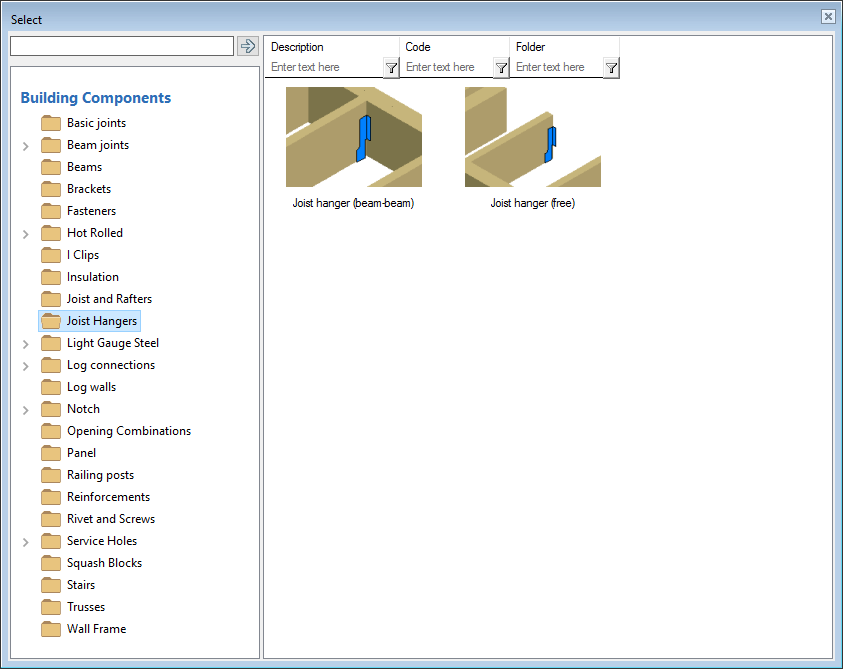
Joints may work as load transferring even if there is no any physical contact between supporting and supported object. Then there have to be a load bearing connector in a joint and a load receiving object. The connector itself does not work as a support. For example a free hanger connected to member end without connection to a header member is not working as a support. Uncheck “Free” selection box for hanger joints to get load transferred from member to another.
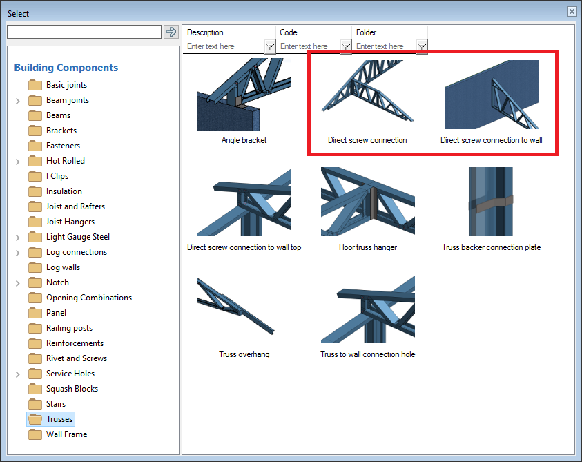
Trusses may be connected to other trusses using joints. Direct screw connections are most effective tool to connect trusses to other structures. Most of the connections in library are single selection connections and they need to be added one by one. Multiple section is available for direct screw connections. User selects connecting members (trusses/walls) and defines properties of connectors. System adds connection automatically between truss verticals if they are parallel and close enough each other. Girder truss may work as supporting object for hip end jack truss. In this case joints are always between truss members not between trusses.
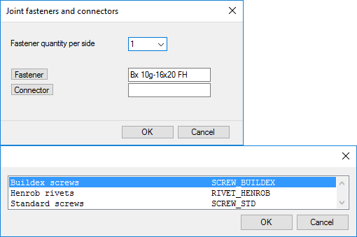
Some joints may have fastener selection. By selecting a fastener user can affect to strength and capacity of joint.
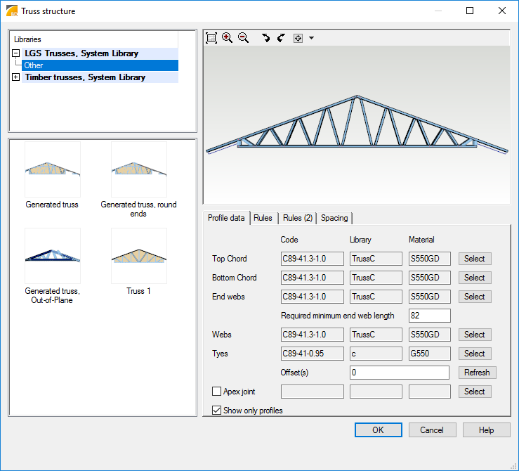
Modeling Truss Members
Truss members are generated inside and flush with truss shape edges. After defining truss shapes use Add/Edit Pieces functionality in Trusses menu to generate truss members. Then neutral axis of all truss members locate in one plane configuration is called in-plane truss. Out-of-plane configuration has chords and webs connected back to back.

Select appropriate cross sections for chords, webs (diagonals) and end webs (end verticals) in Truss structure dialog. Cross sections with proper engineering data for selected building code can be checked under Vertex BD installation system or custom\setup\Building code path\CS folder.
Select appropriate framing rules for truss and finally select appropriate joints between truss members. Use light gauge steel joints between truss members or tick joints as welded. Truss member joints could have engineering capacity or not depending on program setup. All joints in truss engineering are understood as pinned connection nodes. If there are no joints between truss members then there won’t be any pinned connections in analysis model and truss members may act like mechanism that blocks engineering and generates error.
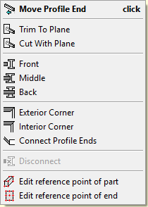
Welded joints can be created also later using ordinary profile connection tools available in grip at profile end. These joints are also pinned in truss engineering analysis.
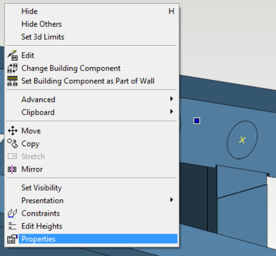
Modifying connection fasteners of the connection is achieved by the Properties of the connection. Quantity of fasteners can be changed there which affects to load bearing capacity of the joint.
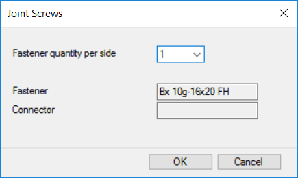
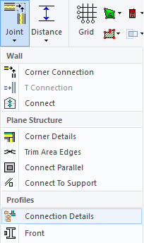
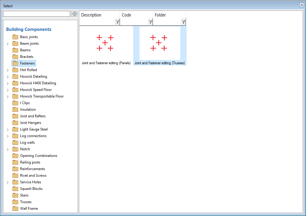
Using Fastener pattern editing from Joints/Connection Details the number of fasteners or fastener type can be changed. Fastener selection affects to load bearing capacity of joint.
There have to be truss members in all trusses and truss drawings should be generated before truss engineering. This is needed because trusses should have labels where engineering results can refer to. Truss labels will be updated during engineering process and engineering label will be added to end of truss label.

Modeling Loads for Trusses
Point, line and area loads can be added into layout using Add point Load, Add Line Load or Add Area Load functionality in Engineering menu when 2D is active. Point and line loads are connected to selected roof or ceiling areas or to selected member if area is not found. Area loads are connected to roof or ceiling area. All loads should be modeled into same drawing-model pair where bearing object is. Point or line loads located between bearing members are divided to nearest bearing members applying multiplier proportional to inverse of distance from load to member.
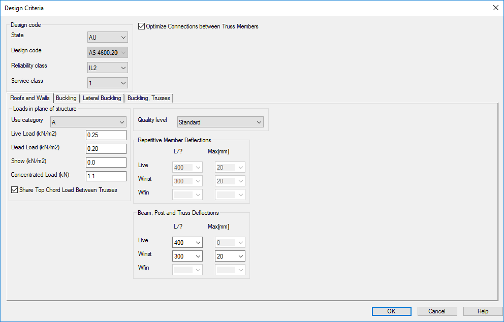
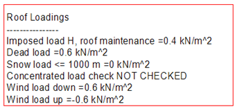
Uniform loads are defined when running Members and Trusses engineering functionality. Live, dead or snow loads can be added. Selected magnitude of loads are applied only to current active 2D layout. These horizontal loads are projected to sloped areas and then load magnitude is reduced compared to area declination. Load magnitudes can be set different for roofs, ceilings and floors and proper tab is shown in dialog only if given type of area exist in active layout. The deflection limits applies for truss chords.
Uniform loads are divided to members based on loading tributary area which is solved during engineering. Greyed areas seen below shows tributary areas and areas without grey color (with background color) are unsupported areas. Hip end trusses with hip drop should have rafters or jack truss extended top chords above hip drop and these members flush with hip slope top should be in contact to hip end trusses members to pass load from roof hip slope.
Only vertical transferred loads from supported structures in same drawing model pair or connected trusses are added to truss loading model. Loads from upper floor levels are not transferred. Truss engineering doesn’t take care of horizontal load components affecting perpendicular to truss side plane. Engineer should design these horizontal loads and structures like bracing carrying horizontal loads independently.
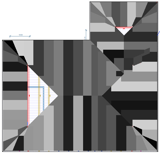
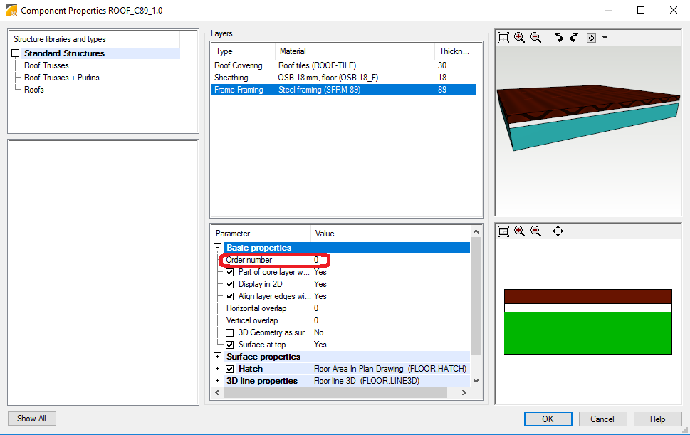
Geometry of area main framing layer is used when solving loading tributary and members getting load from area should be located top flush with main framing layer top face. Main framing layer has parameter 'Order number' with value equal to '0'. Truss bottom chord if located bottom flush with ceiling main framing layer may also get wind load from ceiling.
After the engineering uniform load values are shown in layout rounded with red or green box indicating a validity state of engineering.
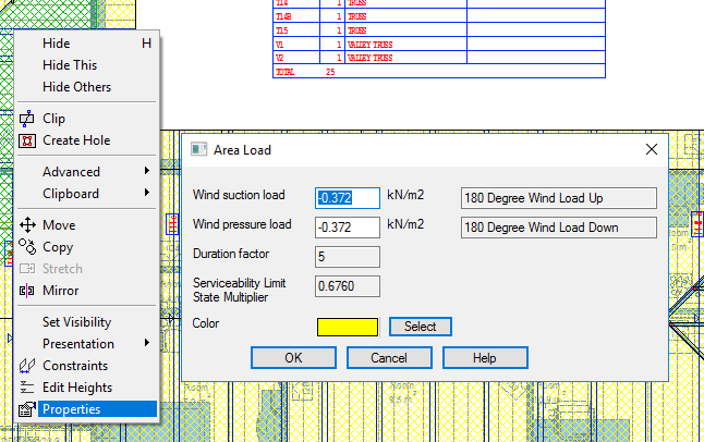
Applying Wind Loads
Building code may offer automatic wind load generation option. Before wind loads are generated, internal wind pressure area should be defined. There is specific function for that purpose in engineering menu. This functions tries to find closed exterior wall chain and adds limiting poly line using wall frame exterior line as a reference. It’s also possible manually add or modify poly line presenting internal wind pressure area.
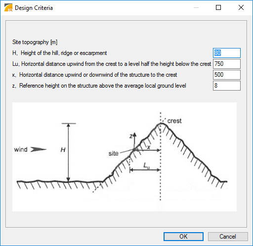
Automatic wind loads are generated based on wind speed, exposure of building site and building enclosure classification. Design criteria defaults should be checked before generating wind loads. Parameters in site topology dialog affects to generated wind load values. Hill height (H), hill width at half height (Lu), site location from top of hill (x) and building height (z) should be given. Wind load generation may fail if building height is not defined.
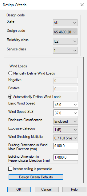
Generation of wind loads creates additional area loads into active building model. Edges of these area loads, magnitude of wind loads and presentation color are then available for user editing. Wind internal pressure is assumed to affect to bottom chord via ceiling area if building type is not defined as “Open” and interior ceiling is not checked as permeable in Design criteria dialog. Ceiling structure 0-layer bottom surface should match to truss bottom chord bottom surface and there should be another layer below ceiling 0-layer to get generated wind loads correct. If ceiling is in wrong height level then “Unsupported object found” errors will arise during engineering indicating that ceiling wind loads are not set to trusses. If building type is “Open” or interior ceiling is checked as permeable wind internal pressure affects to top chords. Enclosed exterior wall chain should exist in building model, because system detects exterior overhang areas and interior areas of chords based on exterior wall chain. Remark: User should generate wind load for ceiling too when ceiling drawing model pair is active. Wind positive external pressure is affecting to top chord via roof slopes. Wind loads are not applied to end verticals of trusses.
Wind is assumed to blow from any direction and user should select the most open terrain exposure category for building site. The user selected building enclosure classification should base on interpretation of selected building code. Wind frictional drag load is not taken into account. Automatic generation of wind loads may fail if building width depth ratio or building mean height does not meet the requirements of selected building code. Then user should define manually all wind loads using uniform load values or point and line loads.
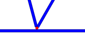
Concentrated Load on Roof
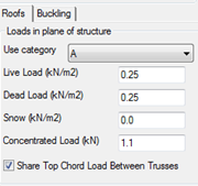
Concentrated load value depends on load category (This may vary depending on building code. For example load category A = 1,1 kN, Australian building code, residential case). Program uses building code specific value by default. Value can be change in roof tab of design criteria dialog. If value is changed, it may be not fulfil anymore requirements of building code. Load is applied as a half of this value to top chord by default and full for bottom chord (This may vary depending on selected building code). Load dialog allows user to select if load is shared between top chords or not (See picture below). Concentrated load is applied into middle of span and near bearings.
User Added point Load on Bottom Chord
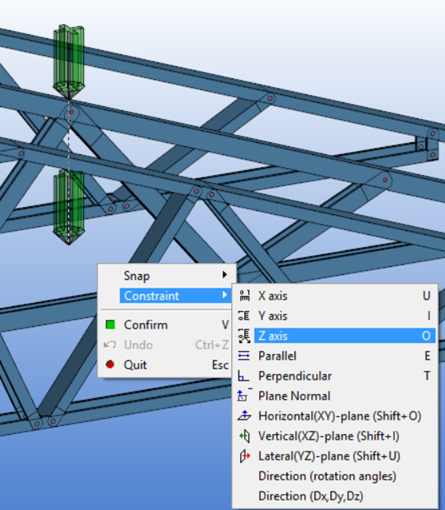
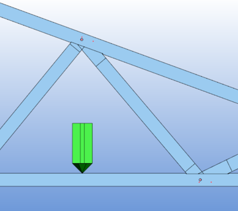
By default point load input drops load to horizontal structure. If point load is added in roof layout load is applied to top chord of trusses. To get point load applied to bottom chord user must move point load in 3D. Select point load and snap to red grip to move load. Use constraint in Z axis to keep selected location in layout and drop load to bottom chord in 3D. Load must be located flush with bottom chord top face otherwise error message arise about load location during engineering.
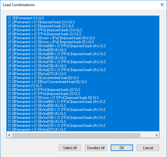
Setting Active Load Combinations
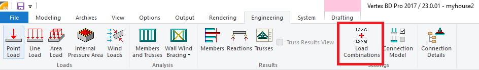
Use Load combinations functionality from Engineering tab Settings group to set active load combinations. A set of load patterns are generated during the design and all these load patterns are run through selected load combinations to create number of load cases. While generating truss load patterns all variable loads like live loads are set on or off for each top chord truss member depending on current location of separating folding point.
If concentrated load value is given in design criteria dialog during engineering truss bottom chord get loaded by moveable concentrated load. This concentrated load is placed just next to bearings and into middle of span or to end of cantilever and it acts only with dead load.
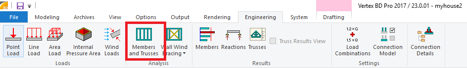
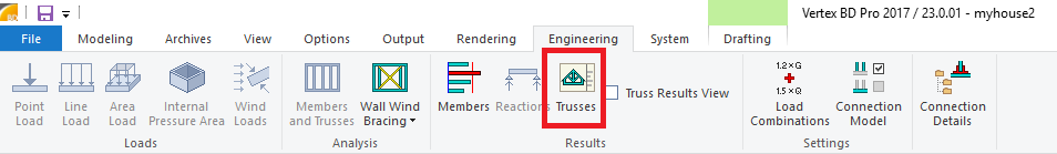
Running Engineering
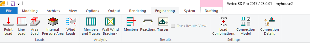
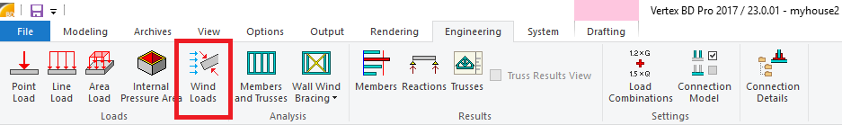
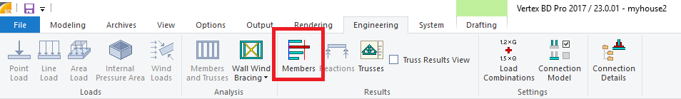
Use Members and Trusses functionality in Analysis group of Engineering menu to run truss engineering. 2D layout should be active. Set design criteria in Design Criteria dialog and then select trusses to engineer.
Truss analysis model is created during engineering. Truss bottom and top chords are continuous and webs are connected to chords with pinned connection nodes. Number of engineering points (up to 7) along finite element between nodes can be set in building code setup.
Euler-Bernoulli beam element and linear first order analysis is used to solve truss structure statistics. Shear deformation can be taken into account by defining (Ay and Az) effective areas of engineering cross sections under building code resisting shear deformation to local direction of main principal axis coordinate system. Ends of beam elements are supposed to be free of any restraint in torsion.
Side-way (out of plane) bucking and torsional buckling effective lengths are base on user input.
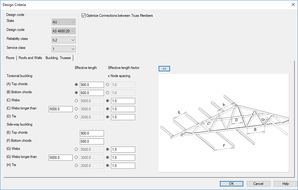
Length for torsional buckling = distance between torsional supports (prevents rotation).
Length for side-way buckling = distance between lateral supports (prevents side-way translation).
Effective length depends on the type of the supports.
Checking Engineering Results
Engineering errors may occur. These errors or warnings are shown after running engineering and user can high light the source point of error by selecting error from Calculation messages dialog.
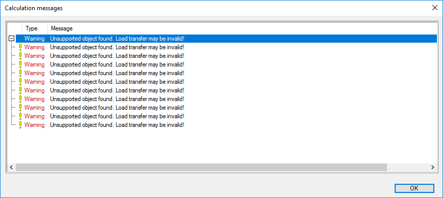
This can be done also in 3D.
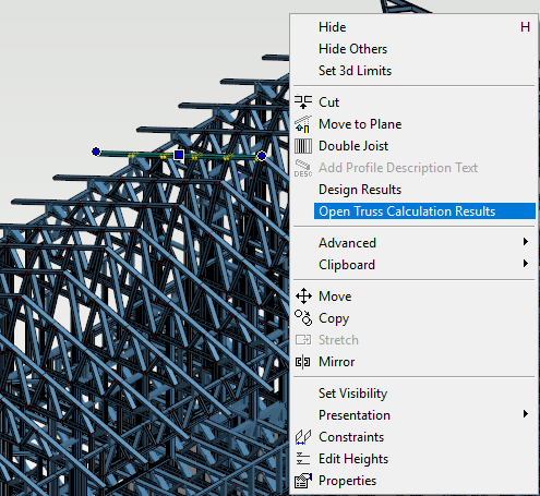
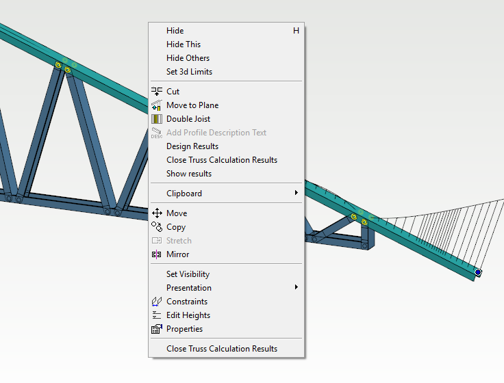
To see results select truss in 3D model and pick functionality Open Truss Calculation results from pop up menu. This functionality hides other element in model and shows selected truss in face view. Failing truss members are shown red in color. When mouse is located to top of member tip text tells more about member engineering results. Clicking 'Show results' link text in tip area utility bars of truss member are shown. Engineering results of one truss member can be exported to Excel using Design Results in contextual menu of member. To return back to model pick Close Truss Calculation results from pop up menu.
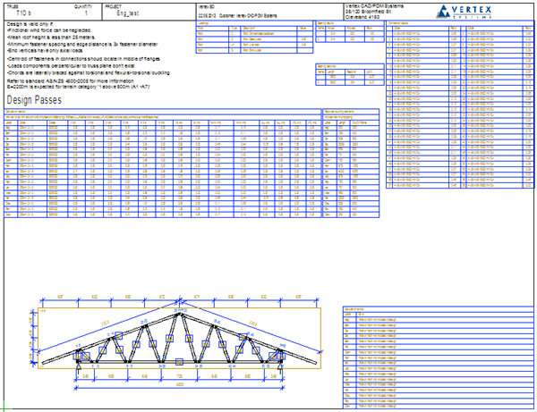
Truss specific engineering results sheet can be opened by Engineering menu Trusses functionality in Results group. Design results sheet shows stress indices of each truss member and connector, if connectors have engineering capacity defined. It also shows engineering error messages, bearing reaction information and spacing list of needed buckling restraint.
Building Code Specific Issues
Engineering Formulas
Engineering equations are based on building code. If further information is needed, implemented equations can be found under building code setup. Depending on building code, buckling engineering may be done by solving required spacing for restraints or engineering member buckling.
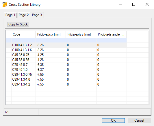
Cross Section Definitions
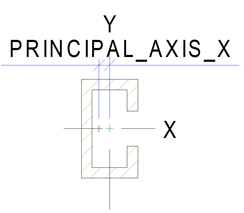
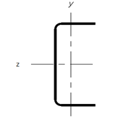
In Vertex BD cross sections for modeling are defined under System settings menu Cross section Libraries functionality. Profile libraries used for engineering should have proper information about main principal axis (neutral axis) location and rotation compared to modeling cross section center. Section modeling coordinate system has x-x axis from left to right and y-y axis from bottom to up, but section engineering coordinate system has z-z from right to left and y-y from bottom to up. All other cross section engineering properties are defined under building codes setup files.
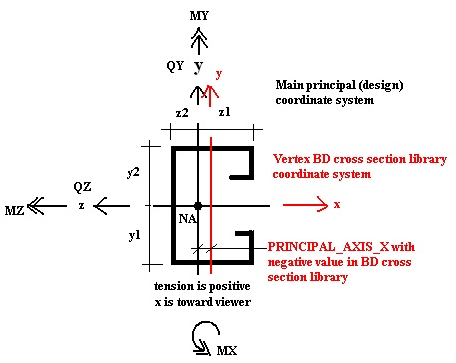
Engineering cross section parameters may vary between building code implementation, because building code specific engineering equations may require specific parameters. Below is shown one set of needed cross section parameters. Parameter names may refer to section engineering coordinates. Because engineering section coordinate system differ from modeling section coordinate system, setup builder should check from engineering equations what is actual meaning of engineering section parameter.
|
Value |
Example |
Unit |
Description of the value |
|
CODE |
C75x32x1.0 |
|
Cross section code |
|
GRADE |
S350GD |
|
Material grade |
|
d |
75 |
mm |
Overall height of cross section to y-direction |
|
b |
32 |
mm |
Overall width of cross section to z-direction |
|
b_f1 |
32 |
mm |
Overall width of flange in negative y side |
|
b_f2 |
32 |
mm |
Overall width of flange in positive y side |
|
d2 |
9 |
mm |
First edge fold dimension |
|
b2 |
9 |
mm |
Second edge fold dimension |
|
r |
2 |
mm |
Folding radius |
|
gauge |
1 |
mm |
Design thickness of material |
|
t_mc |
0 |
mm |
Thickness of metallic coatings |
|
A |
153 |
mm^2 |
Area of gross cross section |
|
effA |
148,7 |
mm^2 |
Area of effective cross section |
|
IX |
49,57 |
mm^4 |
The torsion constant of the gross cross-section |
|
I_w |
25170000 |
mm^4 |
The warping constant of the gross cross-section |
|
IZ |
130900 |
mm^4 |
Second moment of gross cross section area around z-z |
|
IY |
20480 |
mm^4 |
Second moment of gross cross section area around y-y |
|
effIZ |
130900 |
mm^4 |
Second moment of effective cross section area around z-z |
|
effIY |
20480 |
mm^4 |
Second moment of effective cross section area around y-y |
|
y0 |
0 |
mm |
Distance between shear centre and gravity centre, negative value means to negative y direction |
|
z0 |
-24,51 |
mm |
Distance between shear centre and gravity centre, negative value means to negative y direction |
|
y1 |
-37,5 |
mm |
Extreme fiber distance in negative y side (<0) |
|
y2 |
37,5 |
mm |
Extreme fiber distance in positive y side (>0) |
|
z1 |
-9,73 |
mm |
Extreme fiber distance in negative z side (<0) |
|
z2 |
22,27 |
mm |
Extreme fiber distance in positive z side (>0) |
|
E |
200000 |
MPa |
Elastic modulus |
|
G_v |
80000 |
MPa |
Shear modulus |
|
CSWeight |
2,0837825 |
kN/m = N/mm |
Cross section weight |
|
Ply |
1 |
non-dimensional |
Number of cross sections in ply cross section |
|
R_rminBrgE |
30 |
mm |
Allowed minimum bearing length at end support |
|
b_w |
1 |
mm |
Width of web = gauge |
|
d_f |
1 |
mm |
Depth of flange = gauge |
|
Poisson |
0,3 |
non-dimensional |
Poisson constant |
|
SG |
0 |
non-dimensional |
Special gravity |
|
f_od |
500 |
MPa == N/mm^2 |
Elastic distortional buckling stress |
|
f_u |
550 |
MPa == N/mm^2 |
Tensile strength |
|
f_y |
550 |
MPa == N/mm^2 |
Yield stress |
|
effZz |
600000 |
mm^3 |
The effective section modulus calculated with the extreme compression or tension fibre about the local z axis |
|
effZy |
400000 |
mm^3 |
The effective section modulus calculated with the extreme compression or tension fibre about the local y axis |
|
Zy |
434000 |
mm^3 |
Full unreduced section modulus for the extreme compression fibre about the local y axis |
|
Zz |
660000 |
mm^3 |
Full unreduced section modulus for the extreme compression fibre about the local z axis |
|
Zty |
434000 |
mm^3 |
Full unreduced section modulus for the extreme tension fibre about the local y axis |
|
Ztz |
660000 |
mm^3 |
Full unreduced section modulus for the extreme tension fibre about the local z axis |
|
Beta_y |
0 |
non-dimensional |
Monosymmetry section constant about the y-axis |
|
Beta_z |
0 |
non-dimensional |
Monosymmetry section constant about the z-axis |
|
ry |
16 |
mm |
Radii of gyration of the cross-section about the local y-axis |
|
rz |
37 |
mm |
Radii of gyration of the cross-section about the local z-axis |
Earth Quake Design
Building code setups delivered by Vertex neither include earth quake specific loads nor earth quake design.
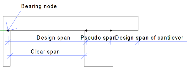
Bearing Nodes
Continuous bearing is modeled as two separate discrete bearings at continuous bearing ends or with one discrete bearing in middle and pseudo span between discrete bearings is used during engineering depending on building code setup. The location of bearing nodes in discrete or in continuous bearings also depends on building code setup. Usually design span is supposed to be a little more than clear span between bearings. Bearing node at end support is located small distance from end bearings inside face toward end of member and bearing node at internal discrete support is located in middle of bearing.