Point Clouds 2025

We presented these reforms in the major version 31.0.0 (2025)
New features and improvements for point clouds
You can now utilize the photos of E57 point clouds in G4Plant, both when viewing the point clouds and when examining the actual pictures.
Navigating between point cloud's scanning points has never been easier. You can click a scanning point directly from the model window or navigate between the points using the minimap.
You can now define the parameters that affect the quality of the surface meshes created from point clouds. Preview the result of the triangulation before performing the actual triangulation on a selected test area.
Divide a large point cloud into smaller segments by splitting. Smaller segments allow you to store and process even larger point clouds.
Use onsite photos while viewing your E57 point clouds
Based on the E57 point cloud file, you can store photographs of the scanning target. We've enabled the option to use these images when examining the point cloud from the scanning point view. Now, you can view both the point cloud and the target photographs simultaneously, or choose to view just one of them.
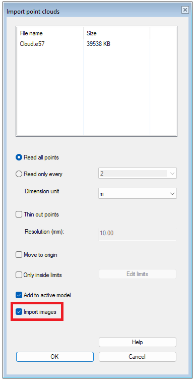
When a user imports an E57 point cloud file into G4Plant, they have the option to import any images included in the file. In the import point cloud Import dialog, we've included a checkbox Import images. When selected, the images are incorporated into the model along with the point cloud. The imported images are saved in the .vxm file when the model is saved. Keep in mind that once imported, these images cannot be removed. If there are no E57 files in the import dialog, the checkbox is disabled. It's important to note that the checkbox can be selected even if the E57 file does not contain any images. During the import dialog, the contents of the file remain unknown.
The program can handle all types of images (pinhole, spherical, and cylindrical) in conjunction with the point cloud. However, displaying images as the point cloud background is only possible with pinhole-type images. To create a 3D view (cubemap) from pinhole images, the following requirements apply:
There should be six (6) images per view.
The images must be square-shaped.
Each direction within the view (left, front, right, up, down, back) corresponds to one image.
While this is a common representation for 3D views using E57 images, other methods exist. The program's functionalities do not support alternative approaches.
To view photographs against the point cloud background, navigate to the Views from scanning points dialog. Activate the Show background images checkbox, and you'll see the 3D view formed by the images taken from that specific point. In the scanning point view, you can rotate the camera and zoom, but movement is restricted (Fix location). If desired, you can hide the point cloud by deactivating the Show points checkbox.
You can enable and disable Fix location when the backroud images are not visible. When enabled the rotation works the same way than with the backroud images. You can hop between scanning points or digitize the location from the minimap. See below for further information. When disabled the movement inside the model works normally.
You can still fly (Navigate) inside the point cloud. If the photos are active when switching to fly, the program will automatically turn them off. The photos are intended to be viewed only from the scanning point. (Vertex ID: VXPLANT-551, VXPLANT-555)
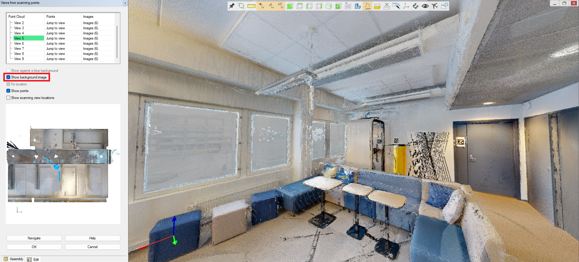
The point cloud in the image above was produced with the camera and lidar of the Matterport Pro3 device.
View photos from your E57 point clouds
You can view the photos that came with the E57 cloud from a View from scanning points dialog. The program opens the photos in a temporary folder that closes when the dialog closes. (Vertex ID: VXPLANT-563)
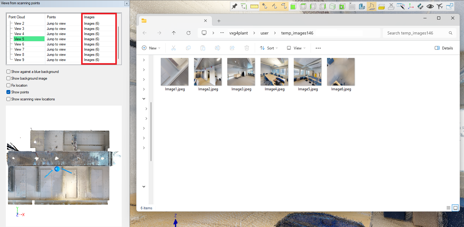
The point cloud in the image above was produced with the camera and lidar of the Matterport Pro3 device.
Hop between scanning points
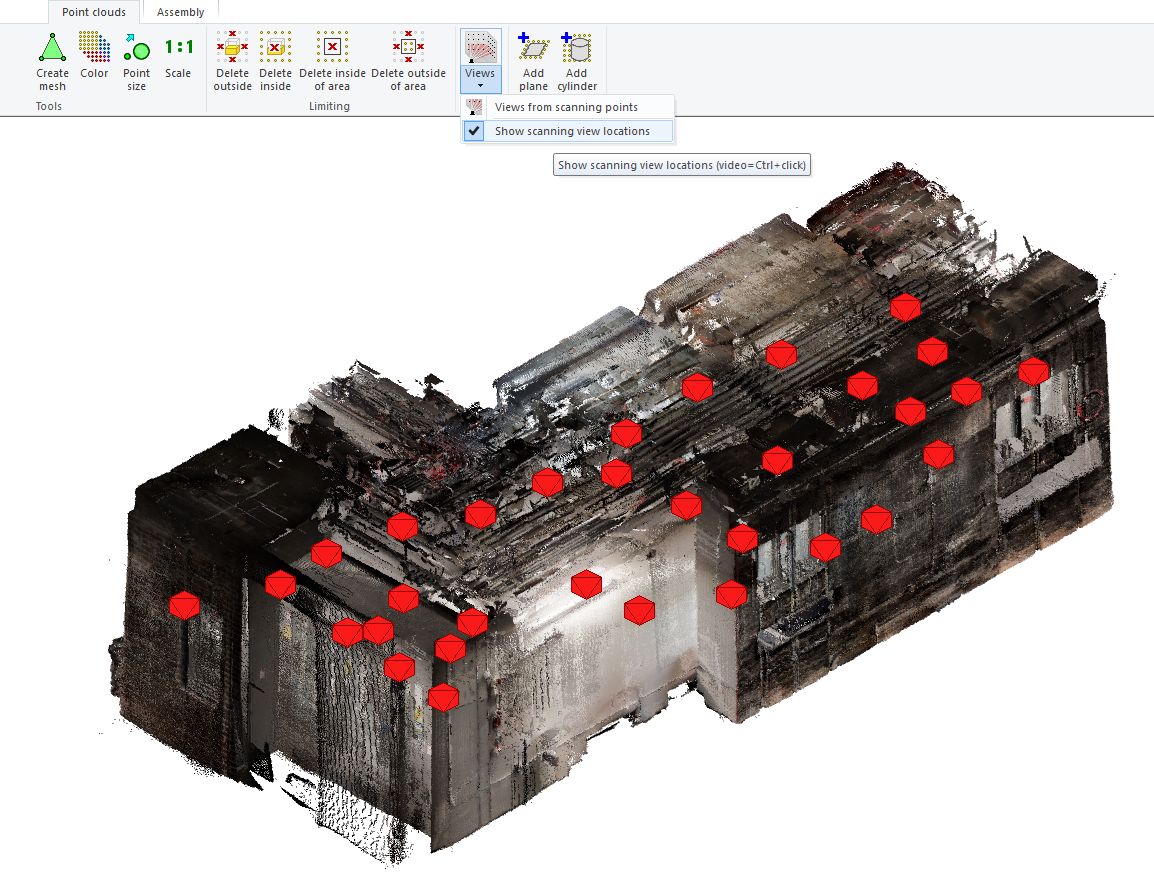
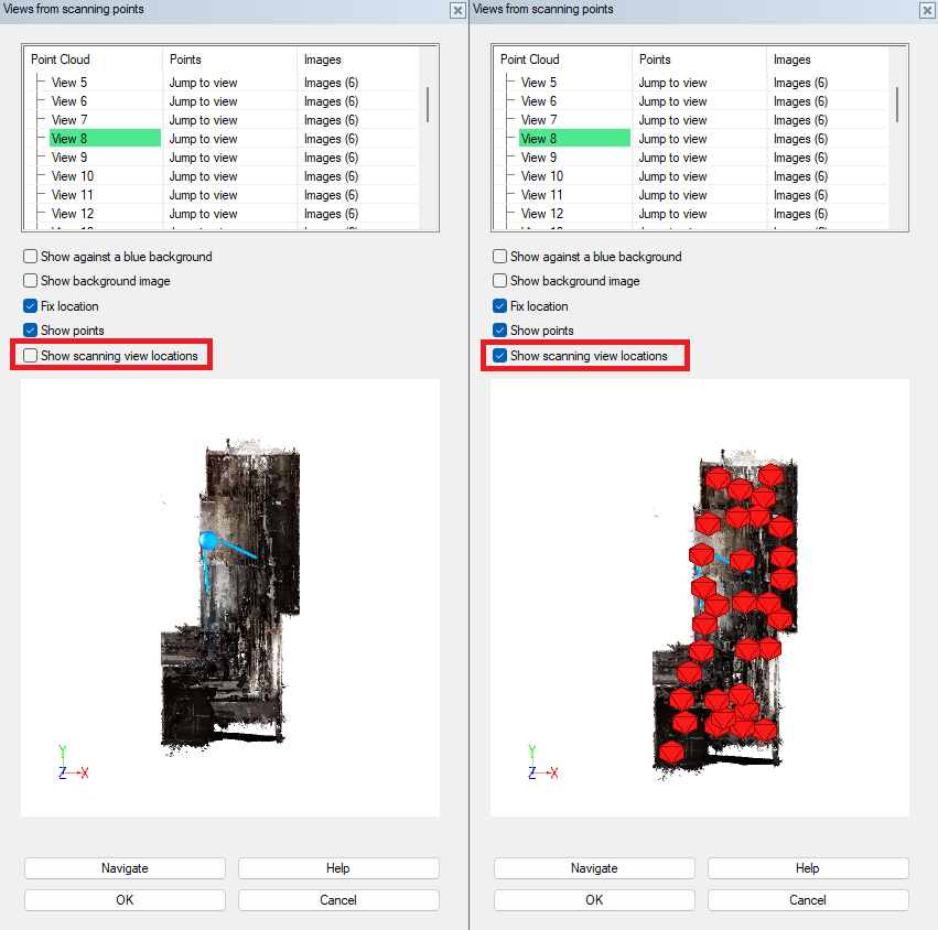
We have enhanced the visualization of scanning point locations by incorporating clear symbols within the point cloud model. These symbols allow you to easily navigate between scanning points by simply clicking on them. You can access the scanning views' locations either through the Point clouds tab by selecting the button Views and its' drop-down menu and the option Show scanning views locations or directly from the Views from scanning points dialog by checking the Show scanning point locations checkbox. When accessing the locations from the Views from scanning points dialog, the program will automatically switch to perspective mode, facilitating a better understanding of the relative distances of points from the selected scanning point. (Vertex ID: VXPLANT-559, VXPLANT-606)
Minimap
The Views from the scanning point dialog now includes a minimap. The map shows you where you are in the point cloud at any given time. It also shows which direction you are looking. This makes observation and navigation much easier when working with point clouds. You can activate scanning view locations and use them to navigate between points.
The minimap has the following features:
The minimap displays a blue ball as a symbol of where you are viewing the model.
The minimap has a sector marked with two lines, which shows the area the user can see in the model.
The minimap displays the locations of pinpoint views if they are set to be visible.
The minimap has the following functions:
The mouse wheel adjusts the map magnification.
You can move the minimap by pressing the mouse wheel.
The left mouse button changes the position.
Ctrl + mouse wheel adjusts the height limit of the minimap.
The Shift key at the bottom changes the perspective of the minimap momentarily:
Releasing Shift restores the original view.
Shift + left mouse rotates the minimap freely.
Ctrl continues to adjust the height limit.
(Vertex ID: VXPLANT-613)
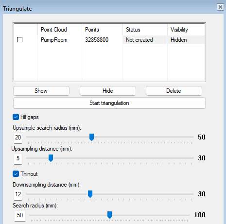
Adjustable parameters for creating surface mesh from point cloud
The user can now adjust parameters that affect the final result of surface triangulation (mesh). In version 2024, the parameters could not be adjusted by the user.
We changed the overall appearance of the dialog to be clearer and updated the functionalities to be more efficient.
The goal of filling the gaps is to fill the gaps left in the surface triangulation. Thinning aims to make the model lighter in terms of size. (Vertex ID: VXPLANT-638)
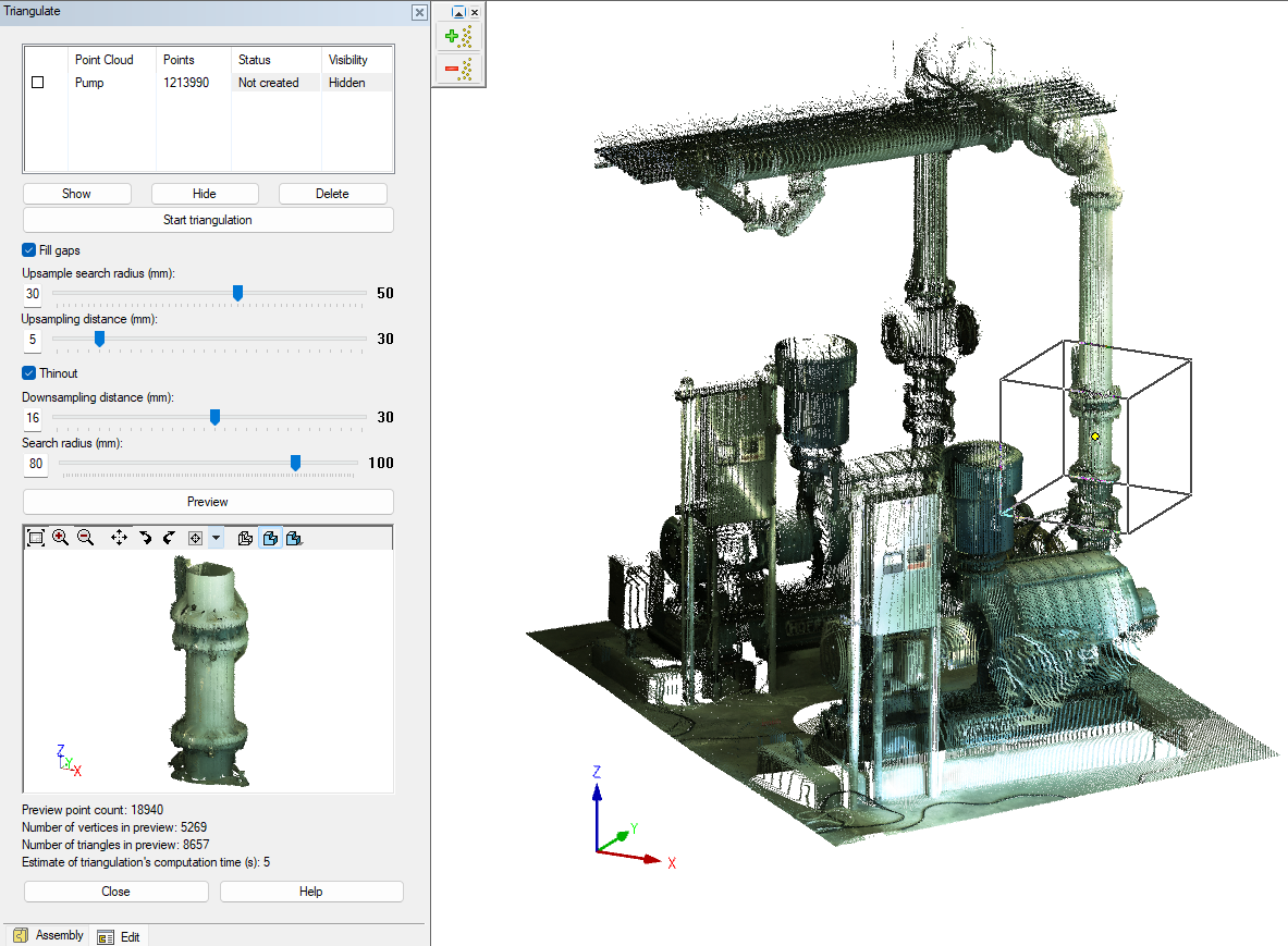
Preview for surface mesh
You can now select a suitable test area from your point cloud. This will help you see for yourself how the selected triangulation parameters affect the creation of the surface mesh. The size of the test area can be easily adjusted when positioning the area.
This makes it easier to select parameters, as you do not have to triangulate the entire point cloud to see how the parameters affect the final result. You can see the effect of the parameter on the surface mesh in the preview window immediately after changing the parameter value.
Below the preview window is a list of a handful of variables and their values. For example, you can see how long it takes to triangulate the active point cloud. (Vertex ID: VXPLANT-642)
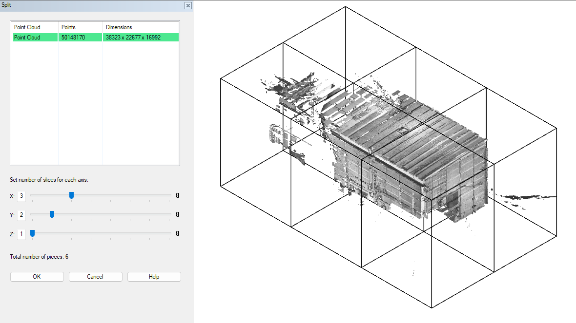
Split point clouds
We have created a new function that allows you to split one large point cloud into several smaller blocks. Splitting allows you to work with even larger point clouds! You can define how many blocks you want to divide the point cloud into.
The program adds the new blocks as parts to the active assembly model. The original point cloud is removed from the assembly. The program deletes a block if the block has no points.
The program adds photos and scanning views to the closest block containing points. (Vertex ID: VXPLANT-651)
Use verify distances tools when views from scanning points dialog is open
You can utilize the measurement tool within the Views from scanning points dialog.
We have enabled the measuring feature for when you're examining the point cloud from the Views from scanning points dialog. You can initiate this action from the ribbon by selecting Verify Distances. This tool allows you to measure distances, angles, radii, and diameters. (Vertex ID: VXPLANT-599)
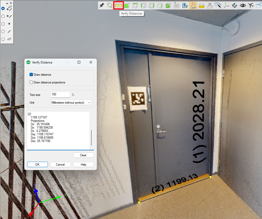
The point cloud in the image above was produced with the camera and lidar of the Matterport Pro3 device.
Combine point clouds
We added checkboxes to the Combine point clouds dialog so you can select which point clouds to merge.
We made it easier to select all clouds by adding a button for that. (Vertex ID: VXPLANT-647)
