These reforms are presented in the major version 28.0.00 (2022)
Piping
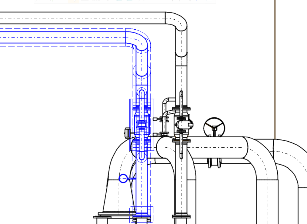
Edit slope also correctly for the supported pipeline
Changing the slope now also works for the supported pipeline. The supports automatically move along the pipeline and to a new height according to their origin point.
The constraints between brackets and pipe centerline are maintained.
Note! If the brackets are in another link assembly, the slope editing works only if the assembly is not set Frozen As Subassembly.
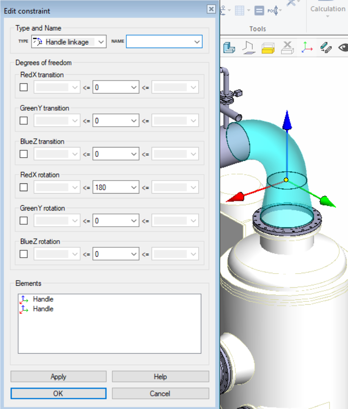
Handle linkage constraint editing dialog improvement
Handle linkage editing dialog layout is now the same as the other constrait dialogs. In the dialog you can change the handle join elements in the same way as in other condition dialogs, for example surfaces. The degrees of freedom of the coffee association are given in the dialogue in the same way as before.
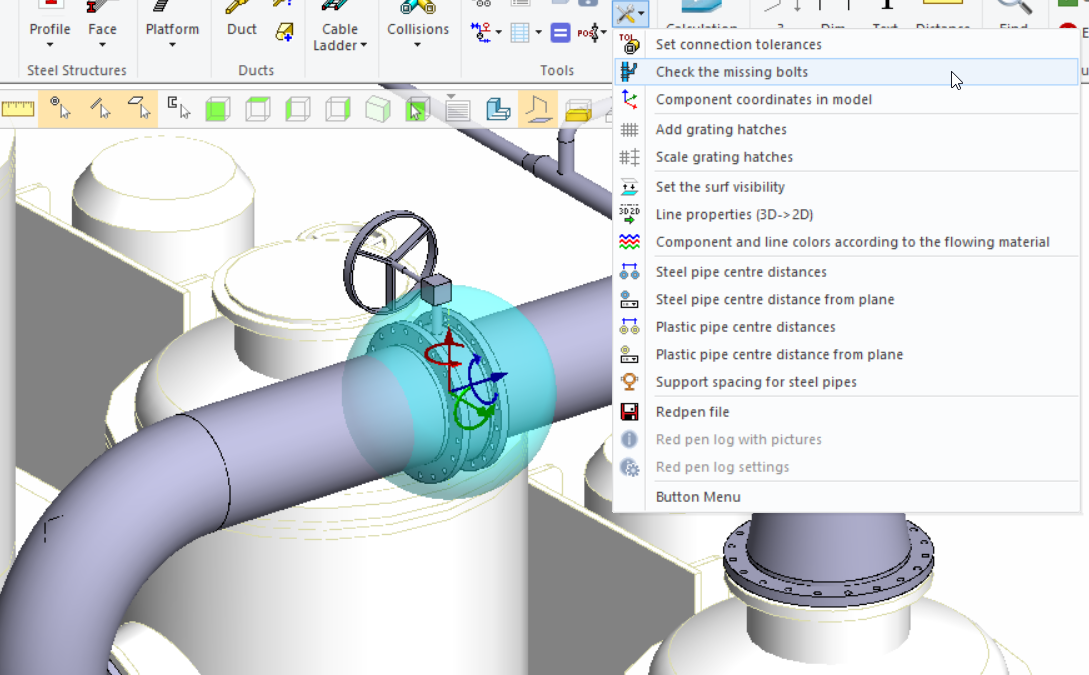
Improvements to check the missing bolts action
The function Check The Missing Bolts has been improved to version G4Plant 28.0. Now the check also correctly takes into account the case of long bolts in valve-between-flanges situation. The function also performs the check more accurately and faster. In addition, the markings of the missing screws no longer accidentally appear in the assembly drawings.
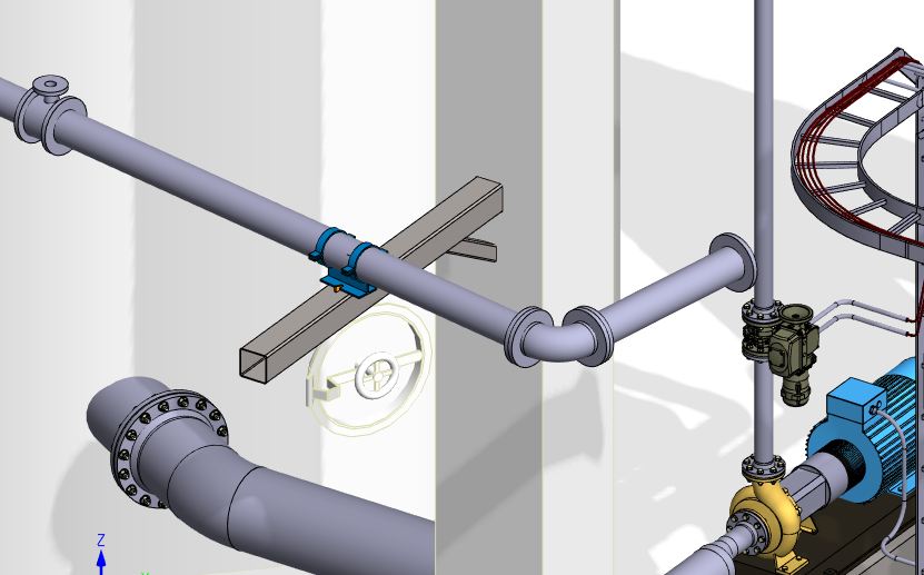
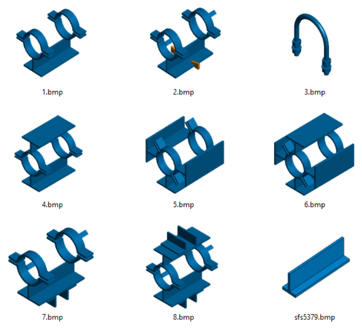
Improvements when adding primary supports from pipe component library
It's now possible to add primary supports from the pipe component library to all types of PIPE-FIXED pipes. This improvment applies especially to those support models, which you have added to the pipe component library yourself. The program adds automatically a coincident constraint between the support and pipe's centerline. We have also prevented you from adding support to the pipe handles accidentally.
Improvements in the choice of material for primary supports
If the user selects a material for the support, then the sub-parts of the support will also receive the same material, excluding the sub-parts of the spring and hanger supports. The material previously selected by the user for the support type can be emptied, in which case the program uses the default materials for the support and its subparts.
By default, insulations are transparent in assembly drawings
In the Add Insulation dialog, the Transparent in Assembly Drawing check box is now enabled by default. This is a more common choice, allowing the insulation to be automatically drawn as transparent to the assembly drawings. Now the cover sheet of the isometric drawing, like other assembly drawings, also follows the transparency setting and other line parameters.
Note! Insulation is only drawn on the cover sheets of the isometric drawing if Insulations to position drawing is enabled in the Others- settings in Isometrics tab.
Hoses
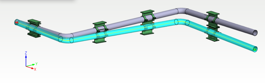
Free location of control points in hose routing
When routing a hose, intermediate transit control points can now be located in version 28.0 freely to the air. Points can also be defined to a certain distance from the selected plane surfaces. The transit part is automatically added to the selected location and gets coincident mate to hose center line. The route of the hose follows these added transit points.
These transit control points can be found under the components library in a folder Components\Others\transit.vxm.
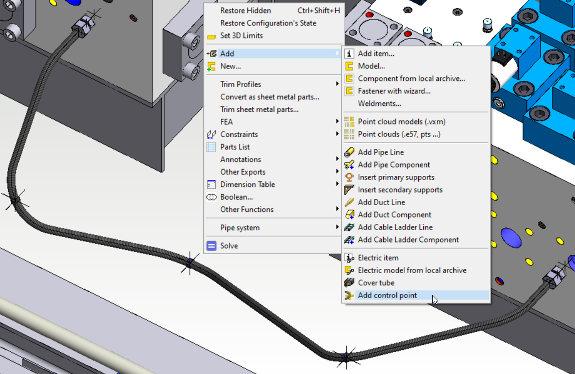
Add control point function
Version 28.0 now also has a separate Add Control Point feature that allows you to add separate control components to the hoses afterwards. The function can be found in the assembly from the context menu Add > Add control point. The control point gets a coincident mate with the hose center line. This also makes the route of the hose follow the positioning of the guide parts.
These transit control points can be found under the components library in a folder Components\Others\transit.vxm.