We presented these reforms in the major version 32.0.0 (2026)
New features and improvements for pipeline welding functions
We significantly accelerated the processing of pipeline welds by completely redesigning the functions.
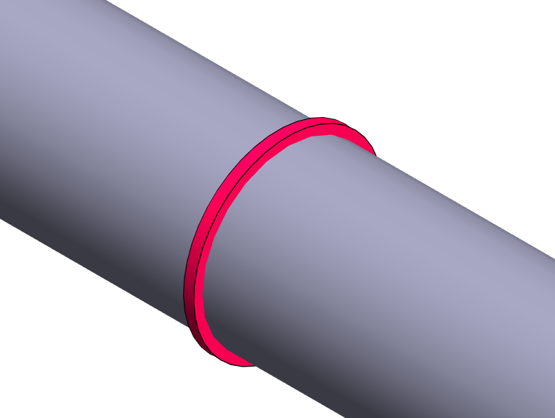
The model representing the weld seam is now disk-shaped, and with it you can access the technical details of the weld in an instant.
The weld list to be added to the isometric drawing now appears in the drawing with one click.
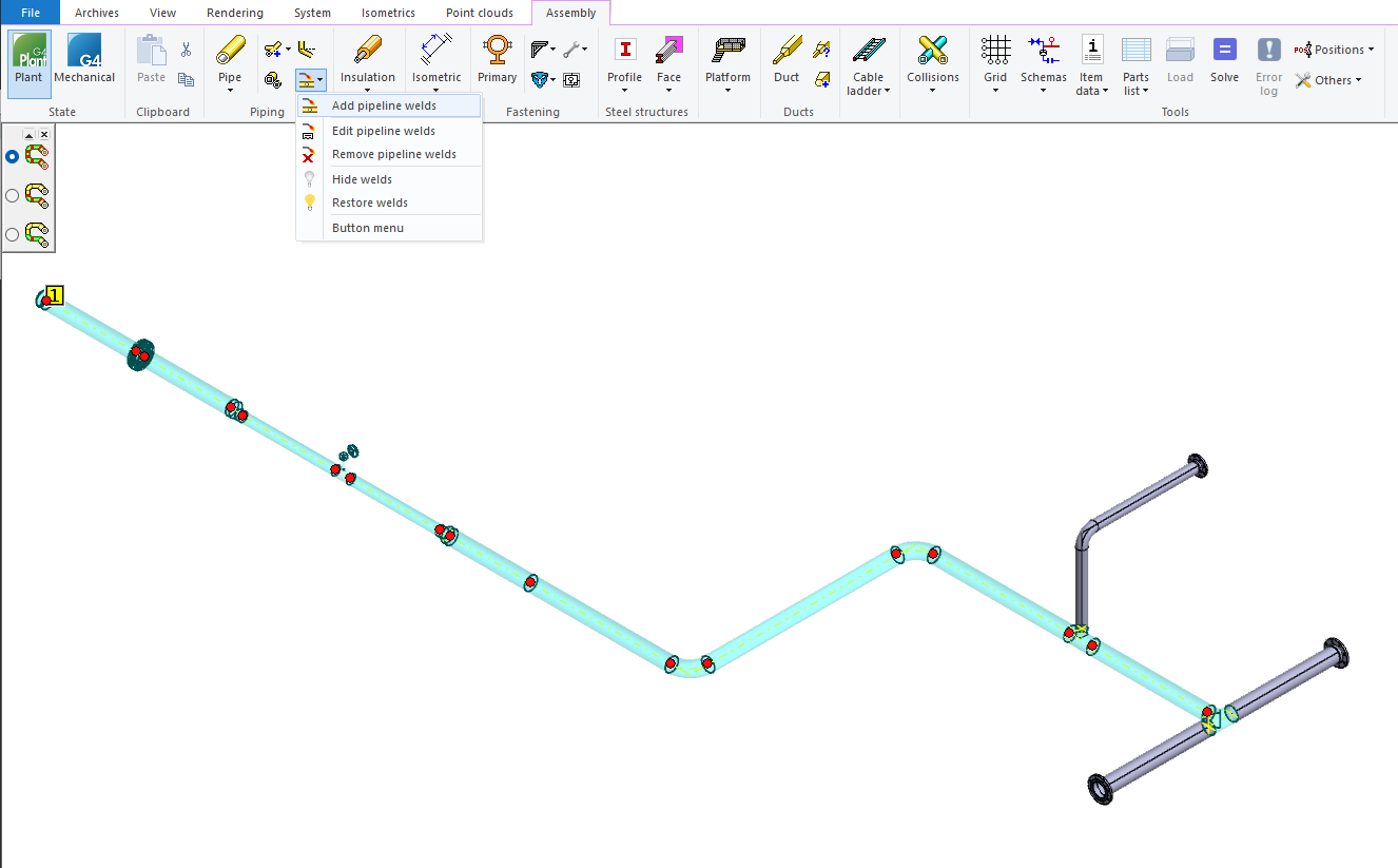
Renewed pipeline weld addition function
The Add pipeline welds function replaces the previous Add weld function. You can now add all welds for an entire pipeline or a pipeline section easily with just a few mouse clicks. Adding welds is now significantly faster than before, as you no longer need to point to each weld seam individually. You can start the function from its dedicated Add pipeline welds button in the program interface, from the context menu under Add > Add pipeline welds, or by selecting an individual pipe component and then using the Add pipeline welds button on the Piping tab. (Vertex ID: VXPLANT-895)
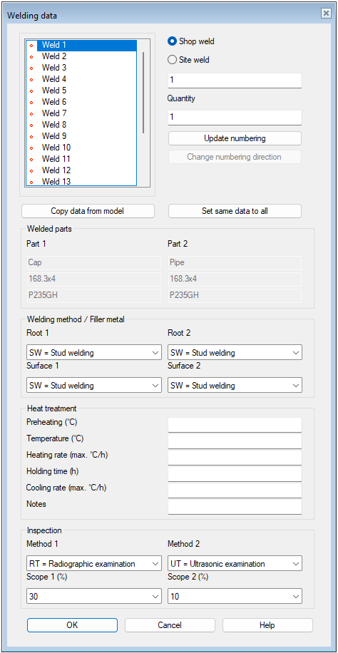
New dialog for welding data
The new Welding data dialog replaces the previous database window for entering weld parameters. In the new dialog, parameters are clearly presented in grouped sections, and the model can be moved simultaneously to view the weld points being added or modified. Handling welding data is now easier, and changes can be easily applied to either a single weld or multiple welds at once. (Vertex ID: VXPLANT-904)
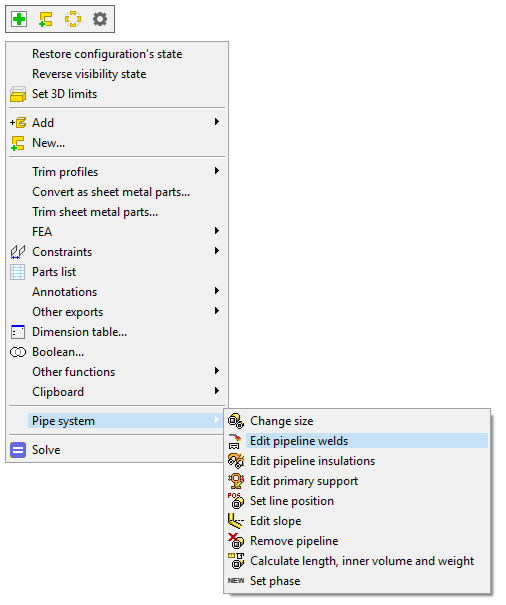
Edit pipeline welds
The Edit pipeline welds function replaces the previous Edit the weld data function. You can now edit all welds for an entire pipeline or a pipeline section easily with just a few mouse clicks. This significantly speeds up the modification of welds between pipe components, as you no longer need to point to each weld seam individually. You can start the function from its dedicated Edit pipeline welds button in the program interface and from the context menu under Piping > Edit pipeline welds when nothing is selected in the model or when a single weld is selected. Additionally, you can double-click a weld to start editing its information. (Vertex ID: VXPLANT-908)
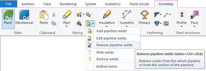
Remove pipeline welds
You can remove all welds for an entire pipeline or a pipeline section at once using the new Remove pipeline welds function. This significantly speeds up and simplifies the removal of welds between pipe components, as you no longer need to point to each weld seam individually. We’ve added a confirmation prompt to ensure that the selected welds are really intended to be removed. This helps prevent human errors. (Vertex ID: VXPLANT-942)
Automatic update of weld data when pipeline size and/or position changes
If the pipeline size or position changes, the weld data for the pipeline is automatically updated with the new data for position, pipe size, and pipe material. This reduces extra work and minimizes the risk of errors. (Vertex ID: VXPLANT-954)
Updated weld model and display of individual weld data
We replaced the old spherical weld model with a new disk-shaped model. The new model is clearer and easier to select in the model than the previous one. In addition, we removed unnecessary line geometry from the model. This makes selecting welds in the model much more straightforward and accurate. (Vertex ID: VXPLANT-960)
If you have enabled attribute display in the cursor, you will now see weld parameters in the tip-text clearly grouped. The tip-text is now formatted in the same way as the weld parameters shown in the new Welding data dialog. This makes reviewing welding data easier and faster. (Vertex ID: VXPLANT-1058)
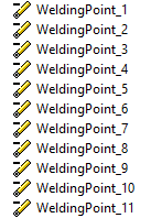
We have individualized the welds in the assembly tree. You will still see the welds in the assembly tree under the name WeldingPoint, but we have added a numeric identifier after the name, such as WeldingPoint_1. This makes it significantly easier to locate a specific weld in the model, as you can identify it in the assembly tree using its number.
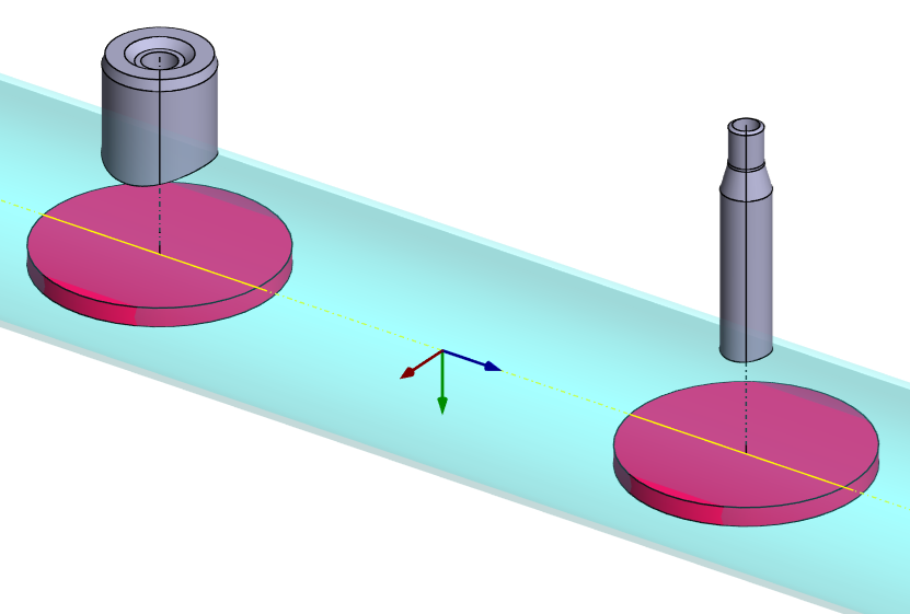
Add weld marks to pipeline branches
When adding pipeline welds, you can now also add welds to OLET-type pipe components as well as to pipe tee-set-ons or other pipe components. Previously, this was only possible by copying existing weld models from one location to another.
You can add a weld between these components and the main pipeline either by selecting the connected branch line or, when the Find the adjacent pipe components for welding search is active, by first selecting the OLET component, tee-set-on pipe, or other pipe component and then the connected main pipeline pipe or other component. The selection can also be made in reverse order, with the same result. (Vertex ID: VXPLANT-1131)
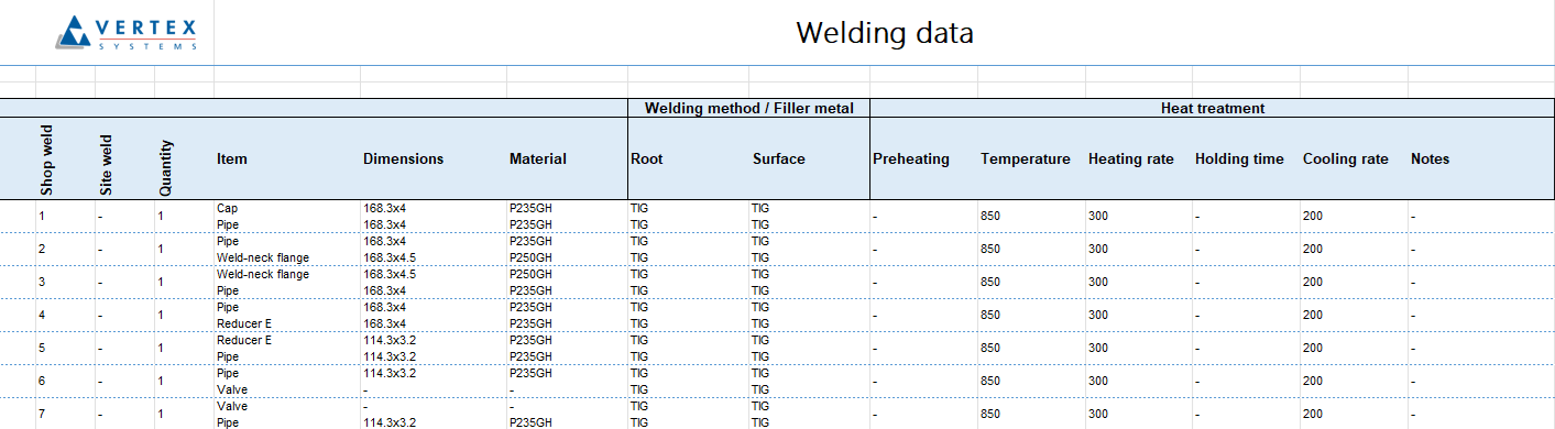
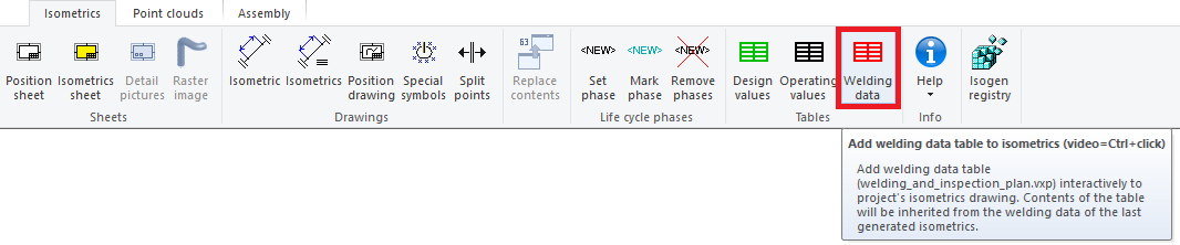
Quick collection of welding data into isometric drawing
You can now gather all weld information related to an isometric into a table by starting the Add welding datas´ table to isometrics function. The function automatically collects both the title block and weld data into a tabular format, which you can then place in the isometric drawing. The symbol can be scaled to the desired size, and the data table follows the size of the title block. This process is now much more straightforward and faster compared to the previous method of pointing to each weld seam individually and placing the table row by row. We implemented these changes by updating the 2D symbol welding_and_inspection_plan.vxp, which now includes a weld list text macro that gathers the weld list. (Vertex ID: VXPLANT-946)
Collect welds from the model into Excel or text file
We have introduced a new function Welding data of pipe components, which allows you to collect pipeline welds and their details into Excel or a text file. With this function, weld data can be listed directly from the model, whereas previously this was only possible through an isometric drawing by adding the list to the drawing. You can find the function on the Assembly tab under the Parts list menu. The function first asks which line positions you want to include in the weld data list. After that, the program opens the data in the Welding data view, where you can export the details either to Excel or to a text file. (Vertex ID: VXPLANT-950)