Adding insulation is easier and faster
Insulate pipeline or duct line with one command
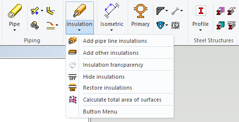
We renewed the insulation functions. You can insulate the following with the function Add pipe line insulation:
-
Complete pipelines and duct lines.
-
Line sections.
-
Single parts.
You can add the insulation with these two functions: Add pipe line insulation and Add other insulation.
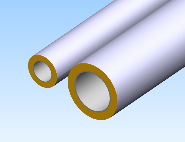
You can add partial insulation to straight pipes while adding the insulation to the line sections or single pipe segments. You can also add the partial insulation to rectangular ducts. The program selects also the connecting pipeline if you choose a single part like a flange, valve or instrument by using the single part option.
The program adds the insulations automatically according to components' type and geometry following the selection you have made in the dialog Adding insulation when you use the function Add pipe line insulation. The program adds the insulations to surfaces automatically according to the selection you have made in the dialog Adding insulation when you use the function Add other insulation.
The item data of the insulation parts are now more precise. The insulation parts are getting more identifying type and size specification from the insulated pipeline or duct line. (PLANT-3265)
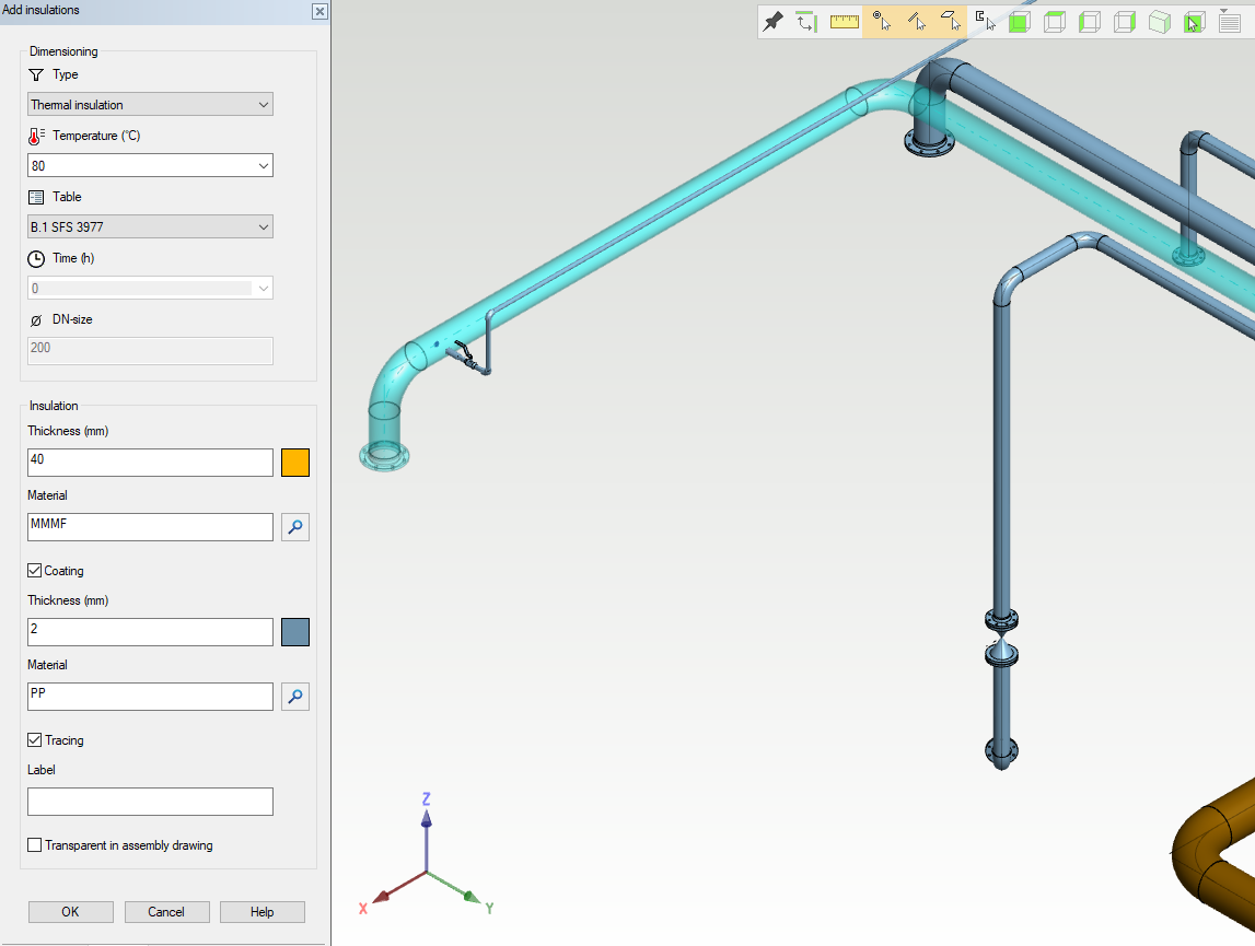
New dialog when adding insulations
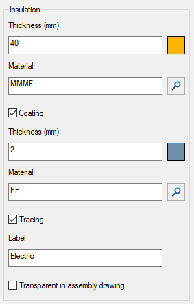
We rebuilt the dialog Adding insulation. The variables which define the insulation thickness still apply only to the insulation of the pipe components. You can freely choose the insulation thickness of the ducts and other parts. The dialog contains these new features:
-
Color selection
-
Material selection (PLANT-3432)
-
Coating selection (PLANT-3425)
-
Tracing selection (PLANT-3459)
The dialog locates itself on the top of the assembly tree.
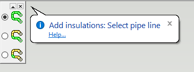
How to select elements for insulation
You can choose how to select elements for insulation after you have started the insulation function:
-
Whole pipeline
-
Segment of pipeline / partial insulation
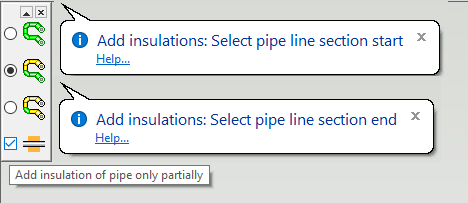
Follow the steps below when you select the option Add insulation of pipe only partially:
-
Select the starting pipe element.
-
Select the starting point for the insulation.
-
Select the ending pipe element.
-
Select the ending point for the insulation.
-
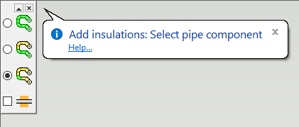
Single pipe component
Define color of insulation
The dialog Add insulations contains buttons for the color of the insulation itself and the coating of the insulation. The program remembers the defined colors even if you reboot the software. The default color for the insulation is yellow (color number 244). The default color for the coating is grey (color number 114). You can restore the default color from the dialog Color Selection by clicking the button Use Default Color. (PLANT-2615)
Tracing
You can define the following values from the dialog Add insulation:
-
Thickness, color, and material of the insulation.
-
Thickness, color, and material of the coating.
-
Is there a tracing underneath the insulation. You can write a free label/type for the tracing. The program adds the tracing data to the insulation's item data and it's visible in the parts lists and isometric drawings.
(PLANT-2615, PLANT-3425, PLANT-3432, PLANT-3459)
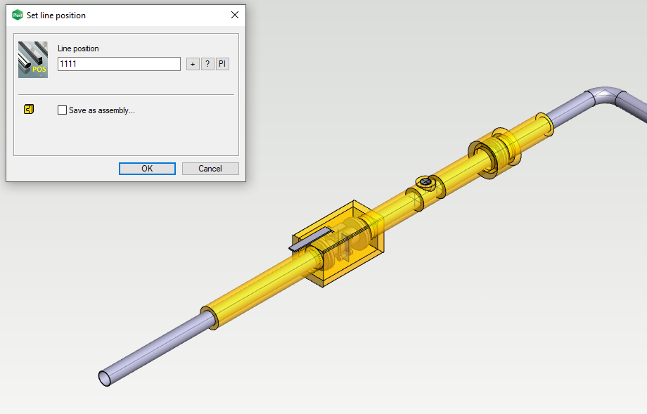
Insulations heritage pipeline's line position
The insulations will heritage the pipeline's line position if it changes. (PLANT-3441)
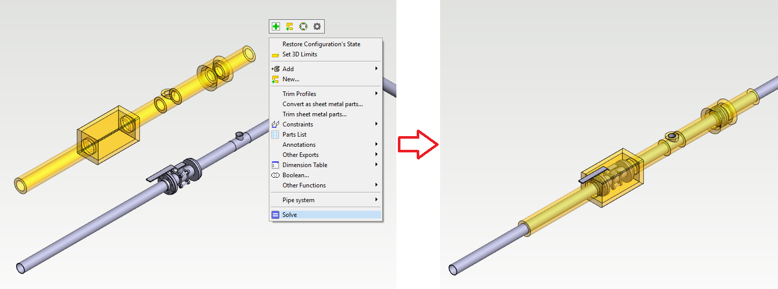
Insulations follow pipeline's movements
The insulation components follow the pipeline's movements and size changes. You need to run the function Solve to make this happen.
The item data of the insulation is no longer written to the pipe component's item data. The program checks the insulation information from the model while it's generating the isometric drawings. Therefore you don't have to remove anymore obsolete item data from the pipe components after you have removed the insulation components. (PLANT-3436)
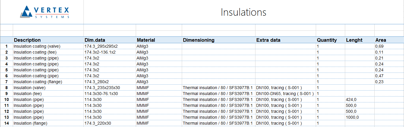
More detailed item data of insulation and improvements to item data updates and parts lists
The program now identifies the insulation components more detailed way by using the component's type and size. The description of the insulation component contains the insulation target. The dimension data of the insulation component contains the inner dimensions of the insulation and the thickness. The additional data of the insulation component contains the information of the insulation itself and the related pipe component's DN size plus the possible tracing. The coatings are also defined with the same detailed method.
The item data of the insulation components follow the changes of the pipe and duct sizes after you solve the constraints of the assembly. The item data is therefore always up-to-date in the model and the Flow item structure. (PLANT-3442)
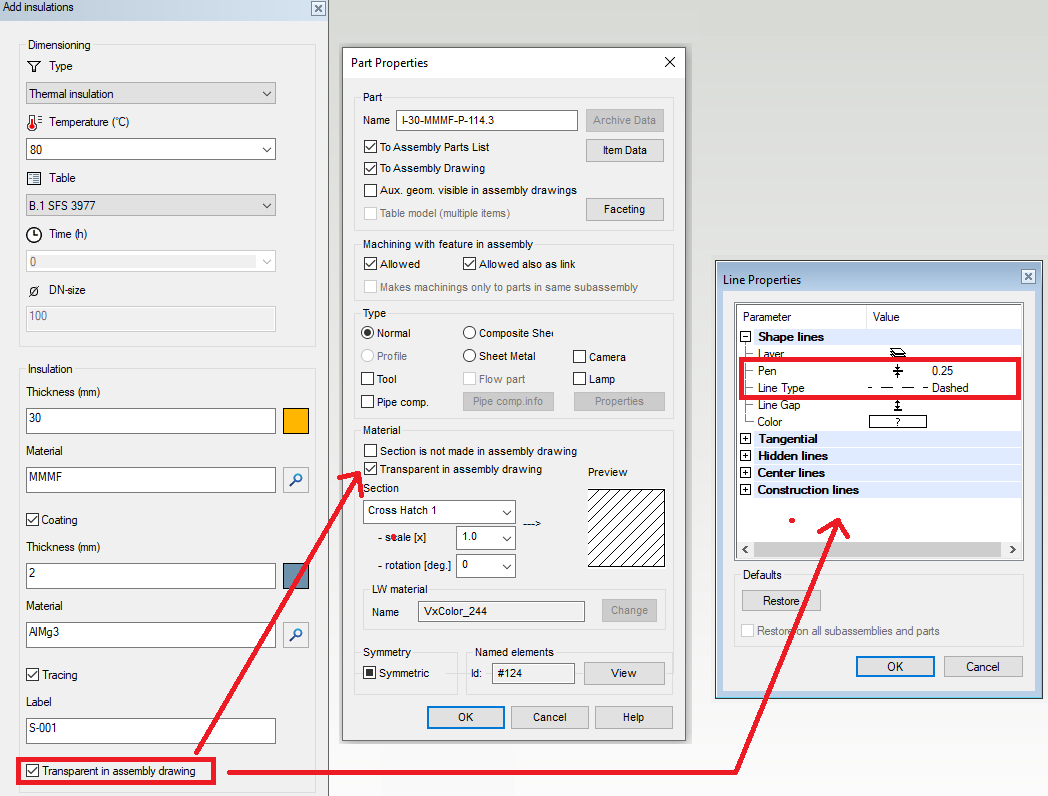
Define insulation as transparent in assembly drawings
You can define the insulation to be transparent in the drawings when you are adding them to your lines by selecting the check-box Transparent in the assembly drawing. The insulation won't cover the line in the drawing anymore. The program draws transparent insulation to the drawing with a thin dashed line. (PLANT-3530)