Reference Grids 2025

We presented these reforms in the major version 31.0.0 (2025)
New features and improvements for reference grids
We completely revamped the user interface, which is now clear and straightforward.
Reference grids will now be their objects at the part and assembly model tree.
Reference grids are drawn in drawings using the new technology and activated for visibility from the drawing properties.
We support reference grids made using old technology with models and drawings.
Revamped user interface and its functions
We completely revamped the user interface for reference grids. The new user interface is clear and its functions are easy to learn.
Creating a reference grid is significantly faster than before, as the user has clear points to define in one place. The positioning and drawing settings can also be found easily as their own entities.
The reference grids will now be their objects within the model and no longer a local part inside the assembly. The reference grid can also be created inside a link part or subassembly in an assembly.
The actual reference grid texts and lines are drawn on the screen using a new technology that is significantly more user-friendly than the old technology.
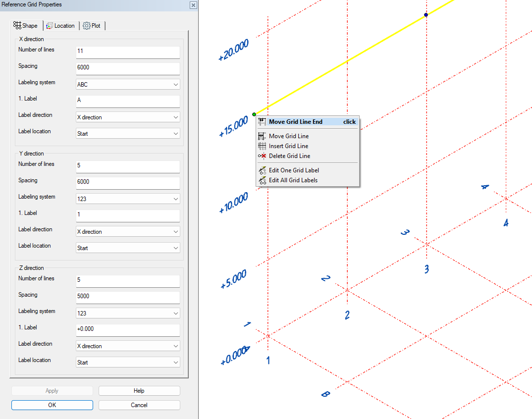
An existing reference grid can also be edited directly from the model using interactive tools. You can move, add, and delete lines and edit annotations either one at a time or in bulk.
You can see the tools by selecting one of the grid lines in the model with the left mouse button. It will turn on the balls at the ends and in the middle of the line. Move the cursor over one of the balls and click the right mouse button. It will open the menu of functions shown in the image below. You can also click the balls with the left mouse button. You start the function Move Grid Line End if you click the ball at the end of the line. You execute the function Move Grid Line if you click the ball in the middle of the line.
The program automatically saves new, manually added lines and changed places in the properties of the reference grid.
Code series can be either letters, numbers, or combinations of these. In the vertical direction, the codes typically reflect layers (for example, 1 floor) or the actual elevation shown in the image below. You can insert typical frames to grid line texts via the Drawing settings by checking the check-box Add frame.
Reference grids implemented using the old technology (version 30 and earlier) are displayed in models and can be referenced with various tools. They can no longer be edited in version 31. (Vertex ID: VXPLANT-674, VXPLANT-734)

Reference grids in drawings
Reference grids are visible in drawings as before. The new features make the usage more straightforward.
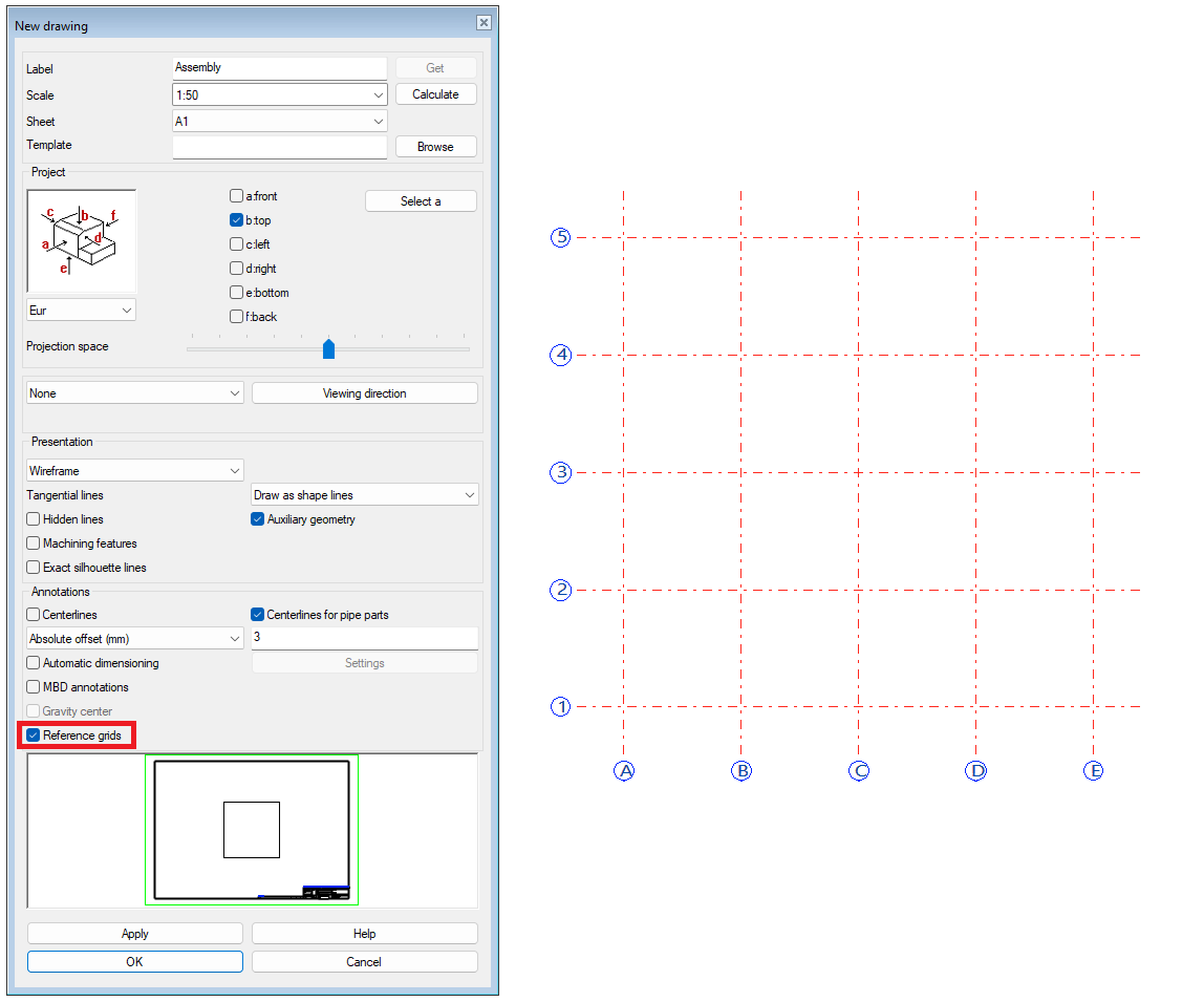
You must choose are the reference grids visible at the drawing when you create a drawing from a model. You find the check-box Reference grids from the Annotation group while you create a new drawing.
The program automatically adds line tags when the program draws the reference grids to the drawing. Frames follow the setups from the model side.
You will still find annotation tools on the 2D side, which you can use to show and hide tags in line grids made with the old technique. (Vertex ID: VXPLANT-678)

