

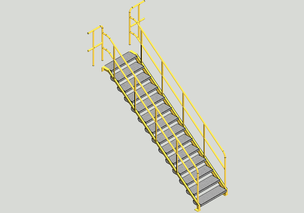
Straight stairs (Model: Ex_Stair1)
-
The model is a measure guided assembly in which the number of stairs varies according to the dimensions given.
Modeling has been started with a local measurable Guide Curve SKELETON. It determines the width of the staircase (WIDTH), floor height (HEIGHT), the depth of the staircase (DEPTH), number of steps (NUMBER), the width of the step (TREAD) as well as the height of the rail (H1).
-
The frame of the staircase is modeled as a profile structure in the Guide Curve.
-
The start and end of the set of step calculations and thus also the direction are bound to the Guide Curve.
-
When the model is varied, the climb and the progression of the stairs remain constant.
-
The stage step has a Tool Feature that makes that allows holes to be machined into the main brackets of stairs.
-
Stairs are modeled on sheet metal. After the variation, you get a drawing of the step with the context menu ”Other Export > Batch export of sheet metal parts”.
-
In reality, the top step should be narrower than other steps .e., only the progression width, and not the step width. The steps are usually dimensioned so that they are overlapping from above.
Download this packaged demo model Ex_Stairs1.vxz (3 174 KB).
-
Save it to your computer or open it directly (the version must be at least 25.0.00).
-
Drag the file onto Vertex G4 (version should be at least 25.0.00).
-
The Model and its Drawing are stored in the project VERTEX_EXAMPLE
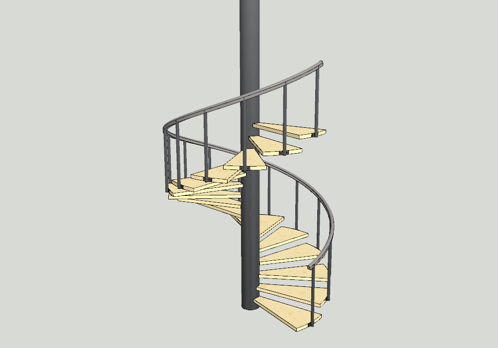
Spiral Staircase (Model: Ex_Stairs2)
-
There is a modeled column and then one step.
-
The steps have been put in series with the "Polar With Pitch" type. In the example, the staircases rotate counterclockwise, but they can also rotate clockwise.
-
The railing column Ex_post is aligned according to the staircase.
-
The railing is modeled with a Guide Curve and a spiral.
Download this packaged demo model Ex_Stairs2.vxz (361 KB).
-
Save it to your computer or open it directly (the version must be at least 25.0.00).
-
Drag the file onto Vertex G4 (version should be at least 25.0.00).
-
The Model and its Drawing are stored in the project VERTEX_EXAMPLE
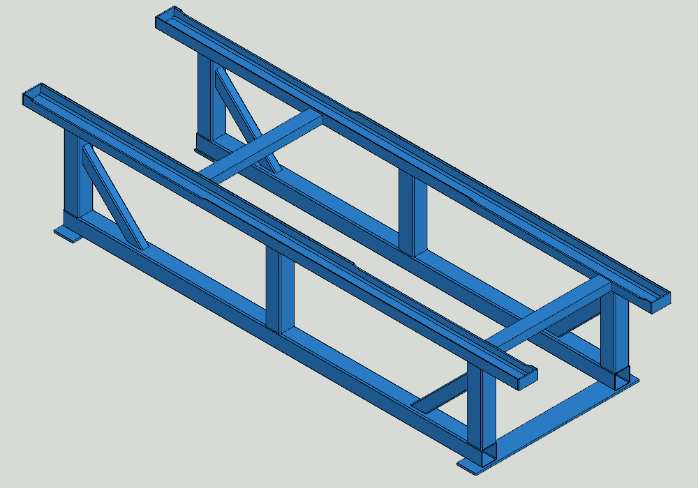
Variable Table Frame (Model: Ex_SaxonTable1)
-
The table body is a typical profile structure model that has been modeled by making a local part "SKELETON". It consists of Guide Curves.
-
In the skeleton, dimension variables (WIDTH, LENGTH and H1) have been added to make the profile structure dimensions easy to change.
-
Profiles have been added by pointing the Guide Curves, while simultaneously sliding the profiles to the front surfaces automatically.
Download this packaged demo model Ex_SaxonTable1.vxz (737 KB).
-
Save it to your computer or open it directly (the version must be at least 25.0.00).
-
Drag the file onto Vertex G4 (version should be at least 25.0.00).
-
The Model and its Drawing are stored in the project VERTEX_EXAMPLE
Scissor Mechanism (Models: Ex_Saxon5, -4, -3, -2 ja -1)
-
The assembly Ex_Saxon4 is a simplified representation of the Lifting Table and consists of other assemblies.
-
First, it is modeled with a local Guide Curves part, which acts as a hinge part for scissors.
-
There are a couple of local parts (GUIDELINE) added to the template that allow scissors to interact.
-
-
The assembly Ex_Saxon1 is a simplified representation of the support arm assembly.
-
It includes local parts: support arm, bushes and bikes.
-
In reality, these parts should be modeled as link parts, each with their own drawing.
-
-
Assemblies Ex_Saxon2 and Ex_Saxon3 are simplified presentations of Saxon assembly.
-
The assembly Ex_Saxon5 is a simplified representation of the lid of Lifting Table.
Download this packaged demo model Ex_Saxon4.vxz (2 681 KB) (It contains other such assemblies) .
-
Save it to your computer or open it directly (the version must be at least 25.0.00).
-
Drag the file onto Vertex G4 (version should be at least 25.0.00).
-
The Model and its Drawing are stored in the project VERTEX_EXAMPLE
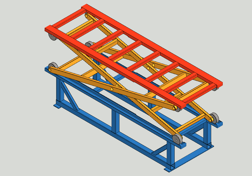
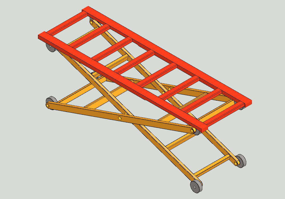
Lifting Table Assembly (Model: Ex_SaxonTable)
-
It consists of two assemblies, a table frame (Ex_SaxonTable1) and a Lifting mechanism (Ex_Saxon4).
-
Lifting mechanism Ex_Saxon4 is not "Frozen at Main Assembly", so you can move the table by dragging it up and down.
-
The model has one Angle constraint with a travel path between angles of 7.5 ° and 80 °. You can simulate movement by driving the angle between these boundaries.
-
In fact, the functionality of the desk table would require additional parts to control the location of the Lifting mechanism during the movement
Download this packaged demo model Ex_SaxonTable.vxz (5 283 KB) (It includes all Ex_Saxon* -models.
-
Save it to your computer or open it directly (the version must be at least 25.0.00).
-
Drag the file onto Vertex G4 (version should be at least 25.0.00).
-
The Model and its Drawing are stored in the project VERTEX_EXAMPLE
Machining Assembly (Models: Ex_MachAssy ja Ex_Machining)
-
The machining assembly shows the use of Tool features. It is best to use Tool features when the structure is first welded and then machined.
-
First, there is a modeled skeleton. Profile has been added to this whit Miter option.
-
In this assembly, a part (Ex_Machining) of the curve and Tool features have been added and positioned whit constraints.
-
The machining is made by context menu function "Machining Features> Execute" situation-specific function. The Tool part (Ex_Machining) is hidden and displayed with the hotkey M.
Download this packaged demo model Ex_MachAssy.vxz (398 KB) (Se sisältää kaikki myös mallin Ex_Machining).
-
Save it to your computer or open it directly (the version must be at least 25.0.00).
-
Drag the file onto Vertex G4 (version should be at least 25.0.00).
-
The Model and its Drawing are stored in the project VERTEX_EXAMPLE.
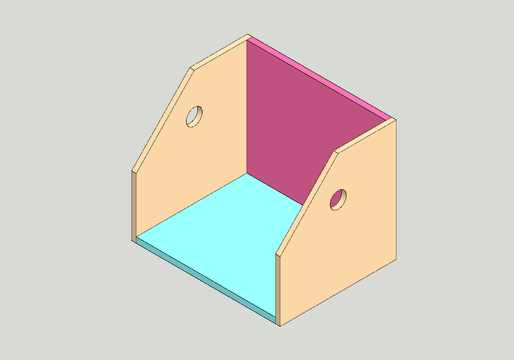
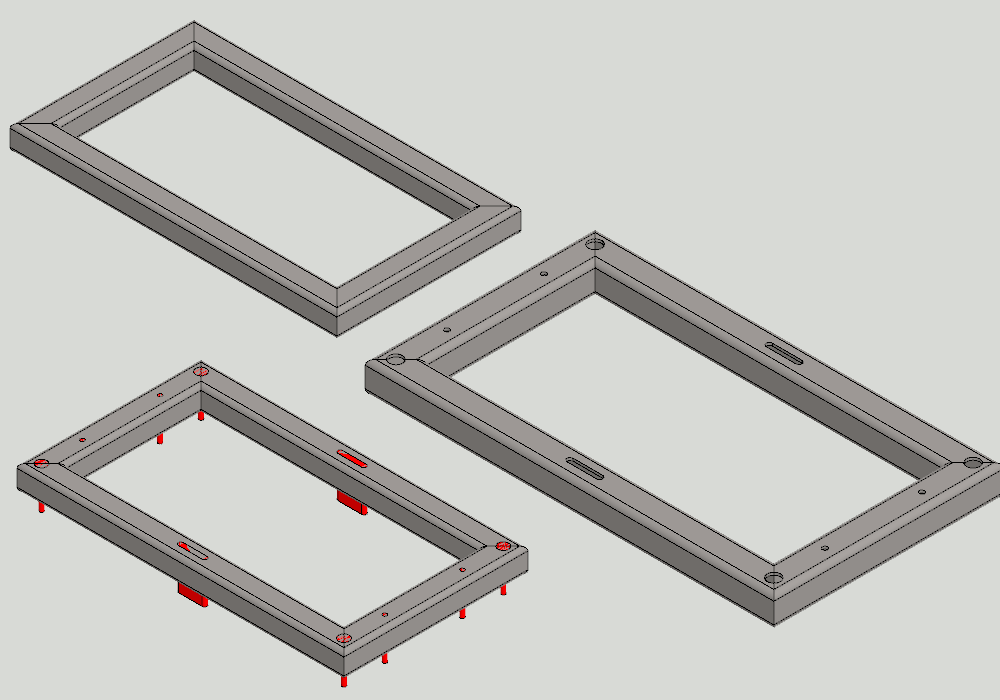
Dimensional Guided Assembly (Model: Ex_SupportAssy)
-
First, there is a modeled skeleton. SKELETON, This controls the width of the carrier (WIDTH), height (HEIGHT), depth (DEPTH) and hole diameter (D).The part has three sketchs.
-
All parts in the assembly are local parts that have been designed to use lines of skeleton part. In this case, they will follow the measurements of the skeleton immediately after the variation of the dimension table.
-
Bottom (PL_1) and side plates (PL_2 ja PL_4) has one sketch, all lines of which have been copied from the skeleton.
-
The back plate (PL_3) has also to the boolean.
Download this packaged demo model Ex_SupportAssy.vxz (105 KB).
-
Save it to your computer or open it directly (the version must be at least 25.0.00).
-
Drag the file onto Vertex G4 (version should be at least 25.0.00).
-
The Model and its Drawing are stored in the project VERTEX_EXAMPLE.
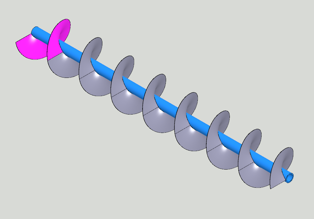
Screw Conveyor (Model: Ex_Helix)
-
The model has two local parts, axes (Axel) and spiral plate (Twist). Twist is in the linear pattern
-
The Twist consists of a Guide Curve that defines the length of twist and the two spiral curves that control the inner and outer diameters. With the spirals you have first made a surface and then a 3mm strong piece on the surface.
Download this packaged demo model Ex_Helix.vxz (438 KB).
-
Save it to your computer or open it directly (the version must be at least 25.0.00).
-
Drag the file onto Vertex G4 (version should be at least 25.0.00).
-
The Model and its Drawing are stored in the project VERTEX_EXAMPLE.
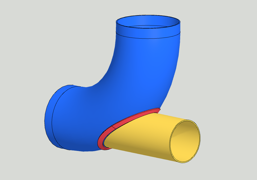
A Pipe Fitting (Model Ex_Collar)
-
The model consists of four local parts, the pipe curve (Curve_Käyrä), related tube (Branch_Oksa), guide geometry (Jig) and collar (Collar_Kaulus). The model has four Representation to show the desired geometry.
Download this packaged demo model Ex_Collar.vxz (487 KB).
-
Save it to your computer or open it directly (the version must be at least 25.0.00).
-
Drag the file onto Vertex G4 (version should be at least 25.0.00).
-
The Model and its Drawing are stored in the project VERTEX_EXAMPLE.
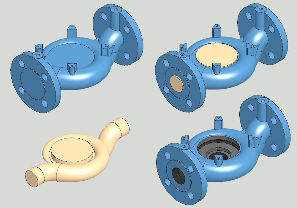
Pump Housing, part machining (Models: Ex_Pump, Ex_PumpBody ja Ex_PumpCore)
This example illustrates a tricky modeling case in which modeling of all features into one sub model is difficult because of the existing geometry. It is much easier to model first the appearance and interior of the body separately, and then only to make the final shape.
-
The model Ex_PumpBody depicts the outer casing of the pump body
-
The model Ex_PumpCore describes the core used to cast the base body.
-
In the assembly Ex_Pump has boolean Subtract.
Download this packaged demo model Ex_Pump.vxz (4 093 KB) (It also includes part models Ex_PumpBody ja Ex_PumpCore).
-
Save it to your computer or open it directly (the version must be at least 25.0.00).
-
Drag the file onto Vertex G4 (version should be at least 25.0.00).
-
The Model and its Drawing are stored in the project VERTEX_EXAMPLE.