

Exercise 9: Boolean. Use one part to machining secont part
This exercise was carried out with version 27.0 (Vertex 2021).
In this exercise you will learn to
-
How to cut a part using another part.
-
How to cut a part using Machining feature of another part.
-
To hide and restore machining features with the M key.
Functions to be used:
-
Boolean.
-
Explode.
-
Part modeling tool.
-
Constraints of assembly: Concentricity and Conicidence.
Get a project that includes the necessary parts
-
Download the zipped Vertex project (VX_AS9.vxz) here.
-
Drag the file from the downloads section of your Internet browser onto Vertex G4.
-
Be sure the models are found (in browser B) in project VX_COURSE_ASSY.
-
If necessary, refresh your browser, if those models VX_AS9-P* are not found immediately.
-
Open the assembly
-
Press

-
Select project VX_COURSE_ASSY.
-
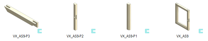
Open the model VX_AS9.
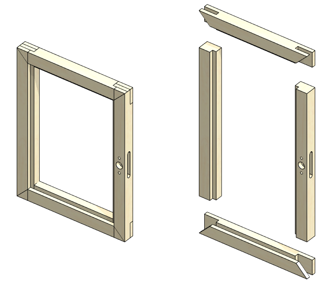
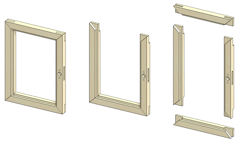
Look at the model. You will notice that the horizontal frames have the shape of a joint, but the joint machining is missing from the vertical frames.
-
Explode the model.
-
OK returns the model to the assembled state.
The first model of this exercise comes from the carpentry industry, as the traditional pin joints made there are perfect for describing the application of the function.
A couple of other exercises are closer to mechanical engineering.
Perform boalean
-
Right-click function: Boolean.
-
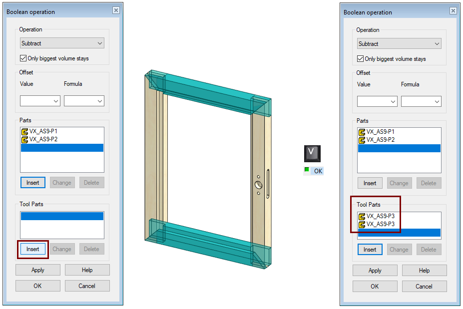
The Boolan operation dialog opens.
-
-
Accept the operation: Subtrack.
-
Under Parts, press Insert.
-
Click the vertical frames to be machined.
-
Acknowledge that the selection of parts is complete
-


-
The selected parts appear in the list.
-
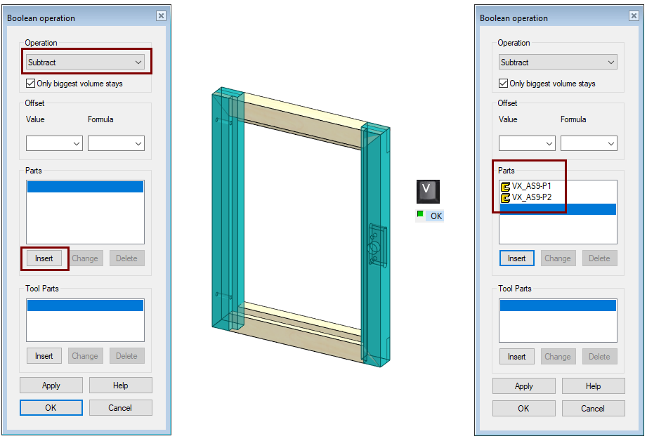
-
Under Tool Parts, press Insert.
-
Click the horizontal frames that act as tools.
-
Acknowledge that the selection of parts is complete
-
-
The selected parts appear in the list.
-
-
OK performs machining.
Check the model
You can either hide the parts or view the model in the explode position.
-
Hide a part with either the right-click function Hiding > Hide or the H key when the cursor is over the part.
Save the model
-
File > Save or click


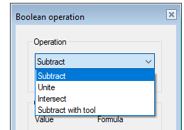
Subtract = The geometry of the other parts is removed from the part.
Unite = The geometry of the other parts is added to the part.
Intersect = Only the part that is common to both parts is left in the part.
Subtract with tool = The tool geometry in the second part is removed from the part.
Create a new assembly
-
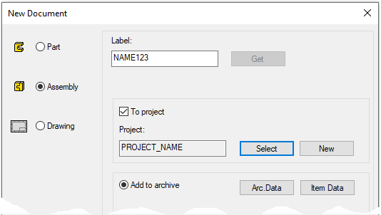
File > New > Assembly.
-
Enter the label (which is also the name of the model and by default will be the name of the drawing).
-
Enter the archive information by clicking Arc.Data.
-
Select the project where the model will be saved.
-
OK.
-
Create the two parts
Create two new parts in the assembly (link parts so that the parts have their own drawing if necessary).
-
Right-click function: New > Part...
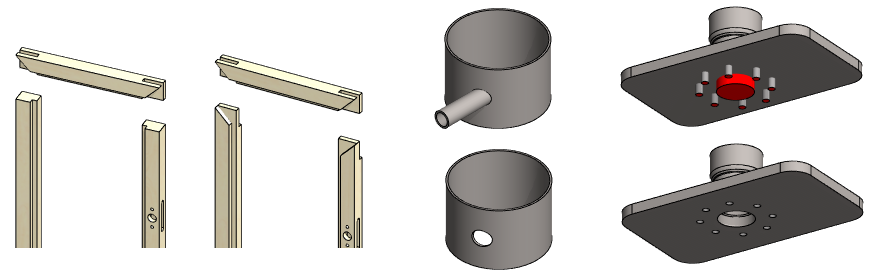
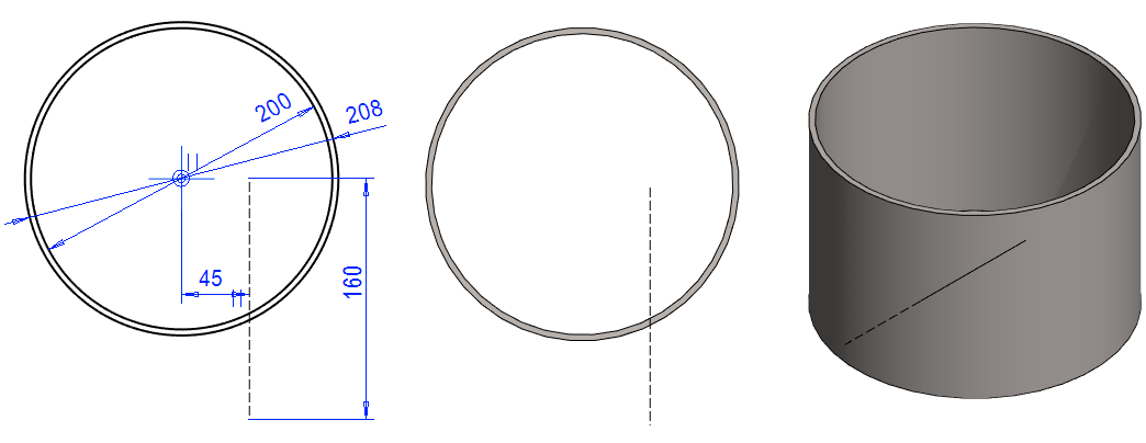
Part 1: Tank casing
-
Right-click function: New Sketch > To horizontal (XY) plane.
-
Sketch the shape.
-
Note the guide line (length 160)
-
-
Operation: Boss - Extrude - In Both Directions. length 140.
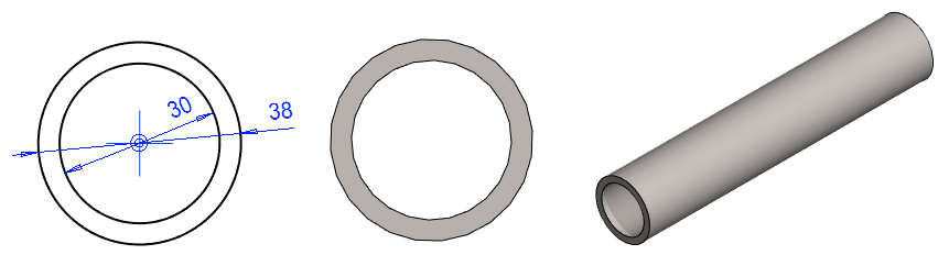
Part 2: Supply pipe
-
Right-click function: New Sketch > To vertical (XZ) plane.
-
Sketch the shape.
-
Operation: Boss - Extrude, length 140.
Position the parts correctly
The parts are locked in the places where they were modeled. Unfix the pipe and put in place using constraints.
-
Click on the supply pipe.
-
Right-click function: Constraints > Release.
-
Add a concentricity constraint to the pipe and the guide line of tank casing.
-
If necessary, change the search method from faces to all geometry.
-
-
Add a coincidence constraint between the end of the tube and the end of the guide line.
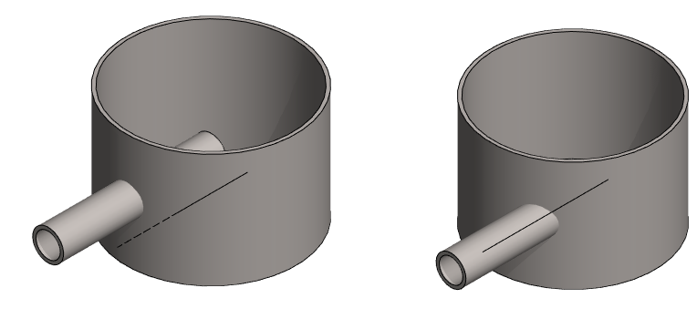
Create a loose hole in the casing for the tube
-
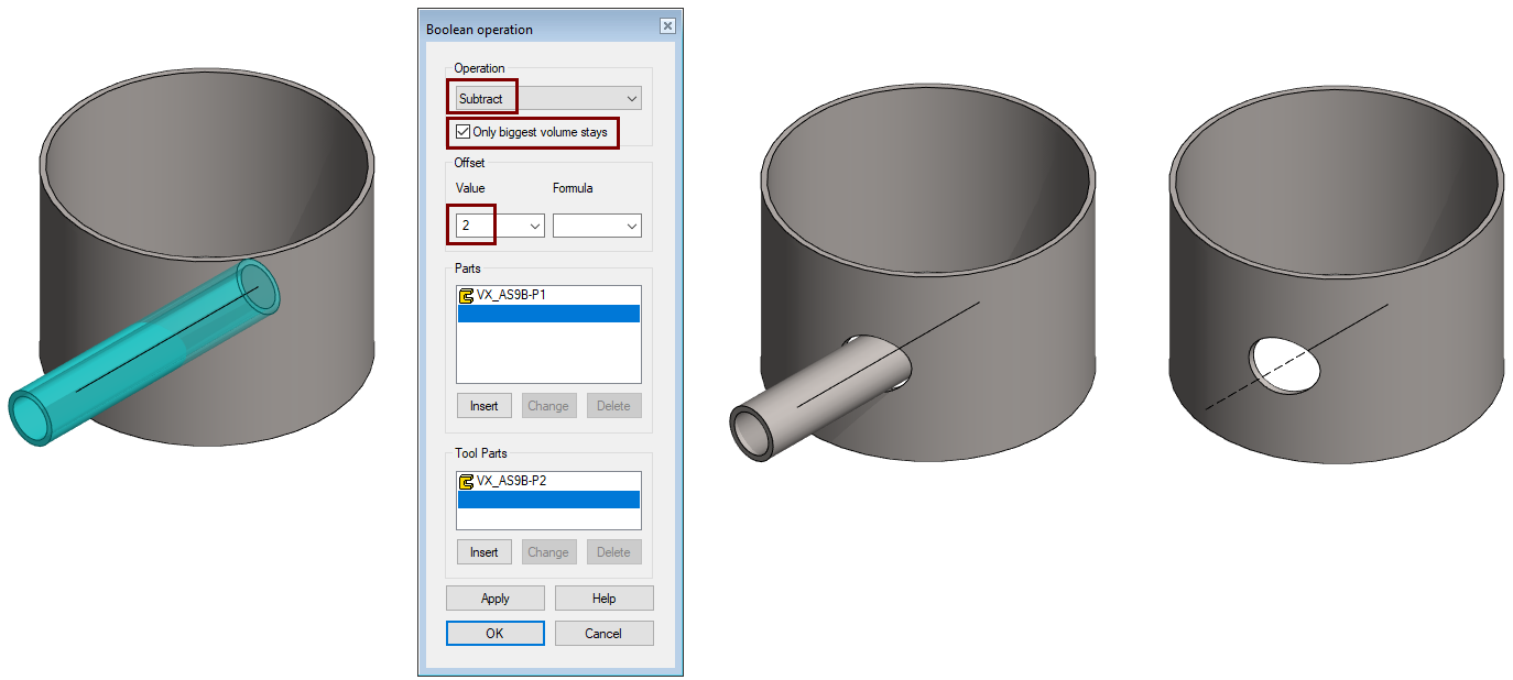
Right-click function: Boolean.
-
Accept the operation: Subtrack.
-
Be sure that the value Only biggest volume stays is selected.
-
Enter the Offset value: 2 (The tool part is "coated" with a 2mm layer, before machining).
-
Select the casing as the part to edit.
-
Select the pipe into the tool parts.
-
OK.
If the Only biggest volume stays option had not been selected, there would have been a "plug" left inside the pipe.
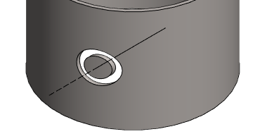
Make the clearance of the hole tighter
-
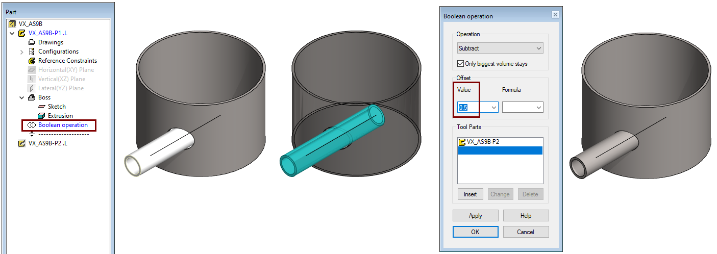
Click the part Tank casing.
-
Right-click function: Edit.
-
In the feature tree, click Boolean operation and perform a right-click function: Edit operation.
-
Or double-click the feature tree in the history section Boolean operation.
-
-
Change the Offset value 2 to 0.5.
-
OK.
-
Select OK to return from part mode to assembly mode.
Save the model
-
File > Save or click
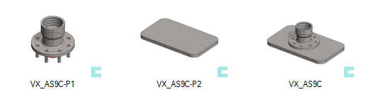
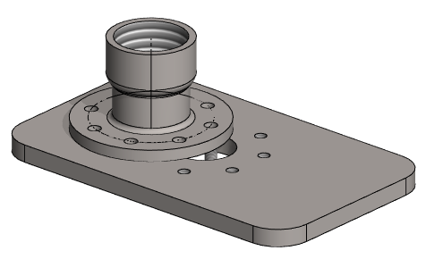
Subract with tool
Get a project that includes the necessary parts
-
Download the zipped Vertex project (VX_AS9C.vxz) here.
-
Drag the file from the downloads section of your Internet browser onto Vertex G4.
-
Be sure the models are found (in browser B) in project VX_COURSE_ASSY.
-
If necessary, refresh your browser, if those models VX_AS9C* are not found immediately.
-
Open the assembly and perform machining
-
Open the model VX_AS9C.
-
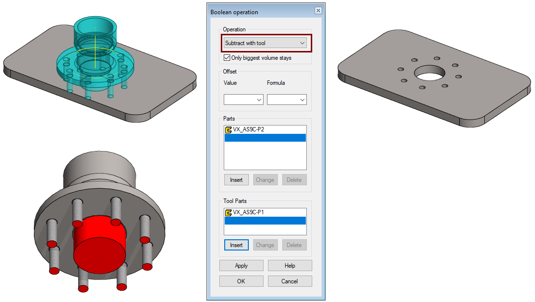
Right-click function: Boolean.
-
Select the operation: Subtract with tool.
-
Select the frame plate (VX_AS9C-P2) as the part to edit.
-
Select the flange (VX_AS9C-P1) into the tool parts.
-
OK.
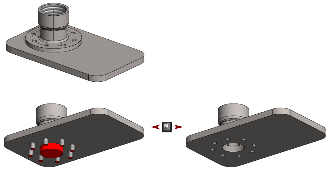
You could also machine the frame plate with the function: Machining features> Execute.
-
If you do this, the original part (VX_AS9C-P2) will not be machined and machining will only be executed in this assembly.
-
After part selection, the machined part can be saved with the right-click function: Machining features > Save Machined as New.
-
This part is saved so that it only shows the so-called Base Feature, that is, the history has been removed from the part.
-
I recommend that this function is used only for the for machining welding assemblies.
When you "machine" with the Boolean function, the part model itself is also edited, so the machining is displayed in the part model itself and its drawing.
Edit the relative position of the parts
-
Drag the flange to another location (There is no constraints have been added to fix it in place).
Create machining the holes in the new place
-
Function: Solve (You can find it on the ribbon or in the right-click menu).
-
Note that updating the model with the F5 key is not enough to perform machining again.
-
In the assembly, you can use the M key to hide and show machining features.
Save the model
-
File > Save or click