

Exercise 5: Suction hood

This exercise was carried out with version 27.0 (Vertex 2021).
In this exercise you will learn to
-
Modeling a part using cross sections and lofting. Thus creating the main shape of the desired hood.
-
To create a sheet metal part with the tangential offset function.
-
To create the Step bends that are required for the Unbend (Flatten sheet projection)
-
To create a 3D unbend.
Functions to be used:
-
Sketching + operation: Cross Section
-
Lofting > Boss (Skinning)
-
Tangential offset.
-
Step Bend
-
Unbend
-
Model the cross sections.
-
Use cross sections to create a part.
-
Create a sheet metal part from the part, using the function: Tangential offset.
-
Create a Step bend on the spline surfaces of the corners.
-
Unbend the part.
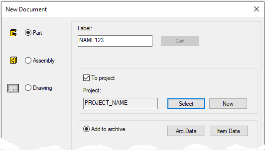
Create a new part
-
File > New > Part.
-
Enter the label (which is also the name of the model and by default will be the name of the drawing).
-
Enter the archive information by clicking Arc.Data.
-
Select the project where the model will be saved.
-
OK.
-
Create the first cross section
-
New Sketch > To horizontal (XY) plane.
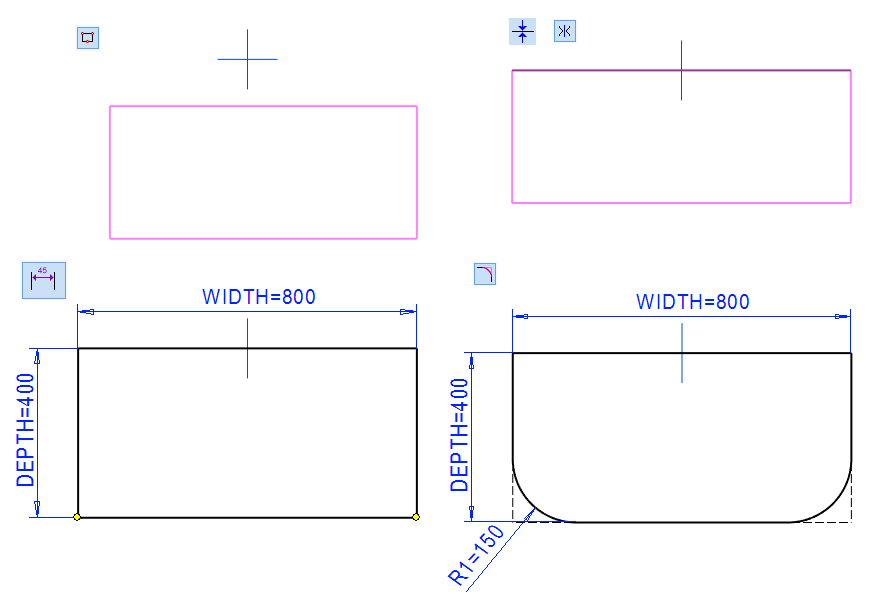
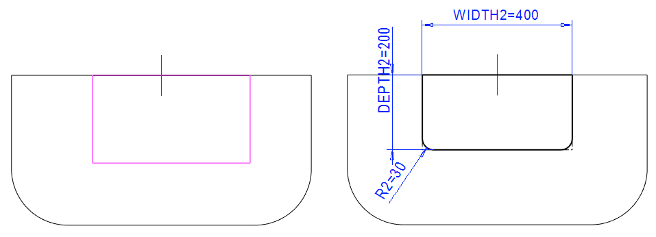
Sketch the shape
-
The function: Two point rectangle.
-
Sketch a rectangle symmetrically about the vertical axis of the central cross.
-
-
Add the Conincident constraint between the upper horizontal line and the central cross.
-
Add the Symmetry constrain between the vertical lines and the center cross.
-
Add the Distance constraints.
-
800 and the formula: WIDTH.
-
400 and the formula: DEPTH.
-
-
Click the two points in the bottom corner.
-
The function: Round.
-
150 and the formula: R1.
-
-

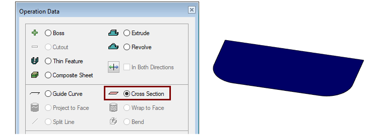
Operation
-
Cross Section.
Create the second cross section
-
Click the first cross section.
-
Right-click function: New Sketch > Parallel.
-
Enter the value: 400 and the formula: HEIGHT.
-
Sketch the shape
-
The function: Two point rectangle.
-
Sketch a rectangle symmetrically about the vertical axis of the central cross.
-
-
Add the Conincident constraint between the upper horizontal line and old line, if needed.
-
Add the Symmetry constrain between the vertical lines and the center cross.
-
Add the Distance constraints.
-
400 and the formula: WIDTH2.
-
200 and the formula: DEPTH2.
-
-
Click the two points in the bottom corner.
-
The function: Round.
-
30 and the formula: R2.
-
-
Operation
-
Cross Section.
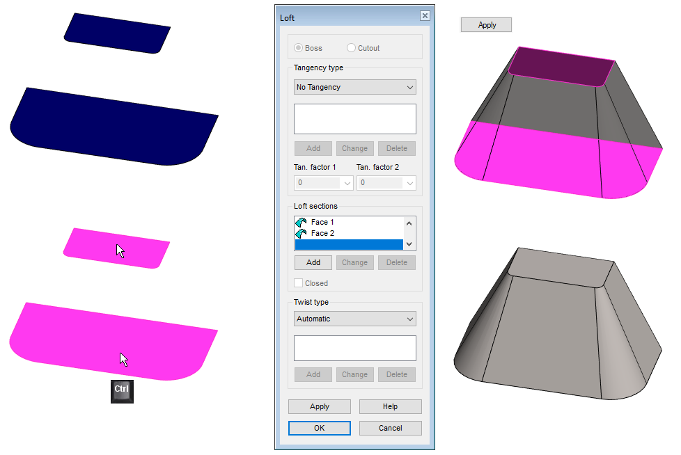
Use cross sections to create a part
-
Click both cross sections (Remember Ctrl key with later cross section).
-
The function: Lofting > Boss.
-
The Loft dialog opens.
-
-
Accept defaults.
-
OK.
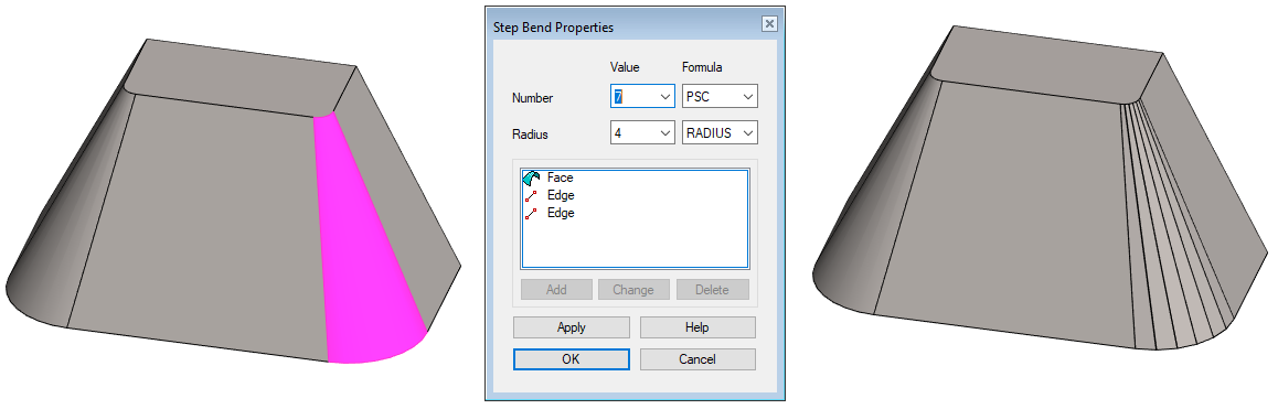
Create step bendings
Step bends must be created on each surface to be separately.
-
Click the face, shown in the figure.
-
Right-click function: Step Bend.
-
Number: 7 and the formula: PCS.
-
Radius: 4 and formula: RADIUS
-
-
OK.
-
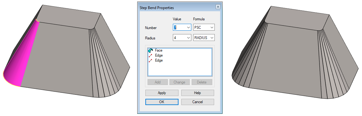
Click the face, shown in the figure.
-
Right-click function: Step Bend.
-
Number: 7 and the formula: PCS.
-
Radius: 4 and formula: RADIUS.
-
-
OK.
The radius of the Step Bend depends on the following factors:
-
Are you adding material In, Middle or Out with the function Tangential Offset (See the next step).
-
From the radius of the bending blade.
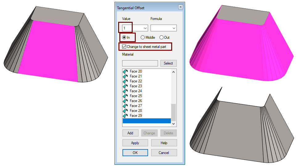
Create a sheet metal part
-
Choose one of the oblique faces.
-
Right-click function: Tangential Offset.
-
Value (Sheet metal thickness): 1.
-
Click: In (the direction the material is added relative to the selected surface.)
-
-
OK.
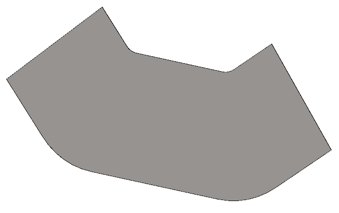
Create a 3D unbend
-
Activate the ribbon of Sheet metal part.
-
The function: Unbend.
-
Accept the face selected by the program or select a face.
Create rebend
-
The function: Rebend.
-
Note that if no features have been added to the unfolded part, the Rebend function removes the Flatten Sheet feature.
Save the model
-
File > Save or click


Further processing of the model (These are presented in Exercise 5 "Drawing on model")
You can add a material item to the model with the right-click function Item Data.
-
These will also appear in the parts list of the model drawing.
You can create a drawing for the model:
-
In the feature tree, select Drawings.
-
Right-click function: New Drawing.
Video
Duration 1m 50s
For the best quality for your video, watch it:
-
In full screen mode.
-
With a resolution of 1080pHD.