

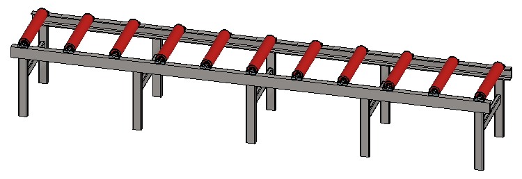
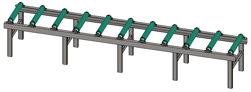
Exercise 5: Part pattern, machining feature and change part
This exercise was carried out with version 27.0 (Vertex 2021).
In this exercise you will learn to
-
To make a pattern of part when a part is added to an assembly.
-
Machining features usage, including link assembly.
-
Change a part.
-
Reconnect constraints.
Functions to be used:
-
Add > Model.
-
Pattern (When a model is added).
-
Constraints: Coincidence,Distance.
-
Change (Part or assembly to another).
-
Machining feature > Execute.
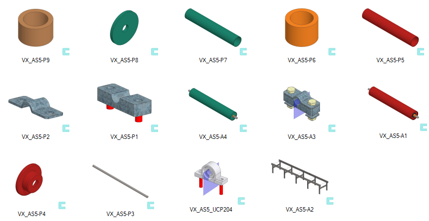
Get a project that includes the necessary parts
-
Download the zipped Vertex project (VX_AS5_PARTS.vxz) here.
-
Drag the file from the downloads section of your Internet browser onto Vertex G4.
-
Be sure the models are found (in browser B) in project VX_COURSE_ASSY.
-
If necessary, refresh your browser, if those models VX_AS5-* are not found immediately.
-
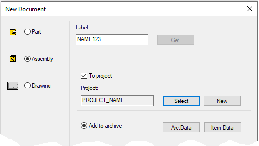
Create a new assembly
-
File > New > Assembly.
-
Enter the label (which is also the name of the model and by default will be the name of the drawing).
-
Enter the archive information by clicking Arc.Data.
-
Select the project where the model will be saved.
-
OK.
-
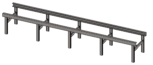
Add the conveyor frame to the assembly
-
Right-click function: Add > Model or add model with

-
Found in project VX_COURSE_ASSY
-
-
Drop the part into place with


-
Press

Add the roller locking pieces in series
-
Right-click function: Add > Model or add model with
-
Choose the configuration: Tarkka (= Exact).
-
From the Auxiliary menu, choose: Create pattern.
-
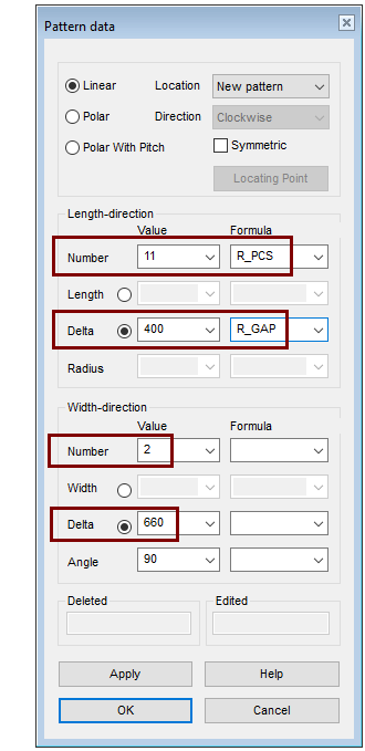
Parameters of patterns:
-
Lenght-direction, Number value: 11 and Formula: R_PCS, Delta value: 400 and Formula: R_GAP.
-
Width-direction, Number value: 2 and Delta value: 660
-
OK.
-
-
Click the location of the auxiliary geometry (preferably) at some point in the part to be added.
-
Click the location of the series from space.
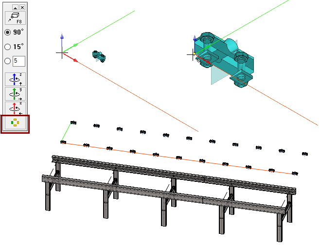
The auxiliary geometry associated with the series (Longitudinal red line and transverse green line) is available for positioning the series, i.e., lines can be part of constraints.
You control the visibility of auxiliary geometry with 

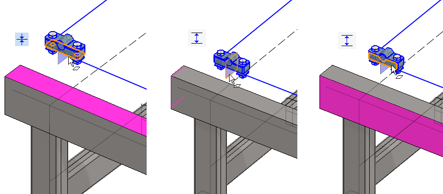
Place the locking piece on the U-beam
-
The lower surface of the locking piece coincides with the upper surface of the beam.
-
Distance of the auxiliary plane in the locking piece from the end of the U-beam: 100.
-
Distance of the outer edge of the locking piece from the outer edge of the U-beam: 12.5.
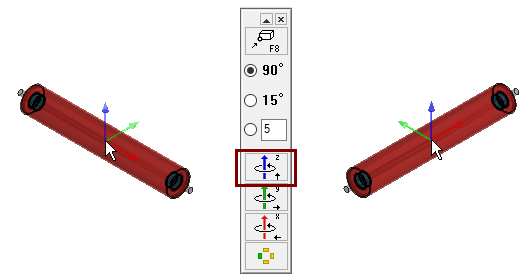
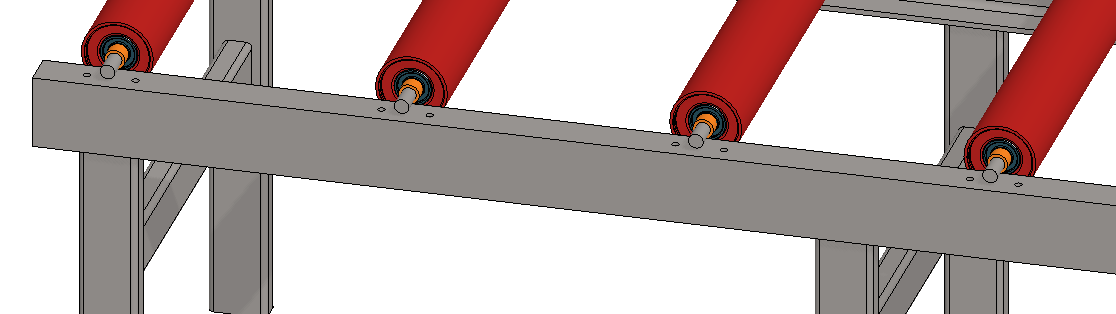
Add the conveyor roller
-
Right-click function: Add > Model or add model with
-
Rotate it around the blue Z axis 90° with auxiliary function: Rotate around the Z axis.
-
Click the location of the series from space.
Place the conveyor roller
-
Add a concentricity constraint between the roller shaft and the locking piece.
-
Add a distance constraint between the end of the roller sleeve and the inner edge of the (upper) locking piece: 2.
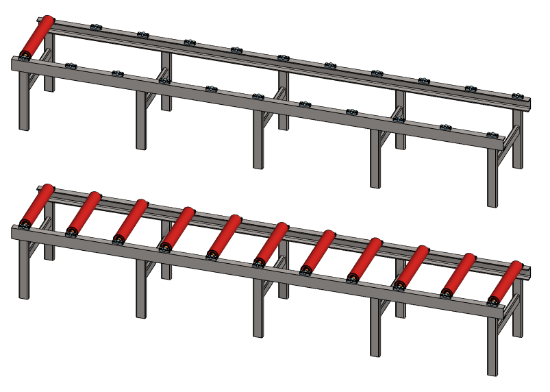
Create a pattern from a conveyor roller
-
Select a roll from the assembly feature tree.
-
Right-click function: Pattern.
-
Lenght-direction, Number value: 11 and Formula: R_PCS, Delta value: 400 and Formula: R_GAP.
-
Width-direction, Number value: 1
-
OK.
-
-
Click to the position of the pattern auxiliary geometry line at the end point of the axis.
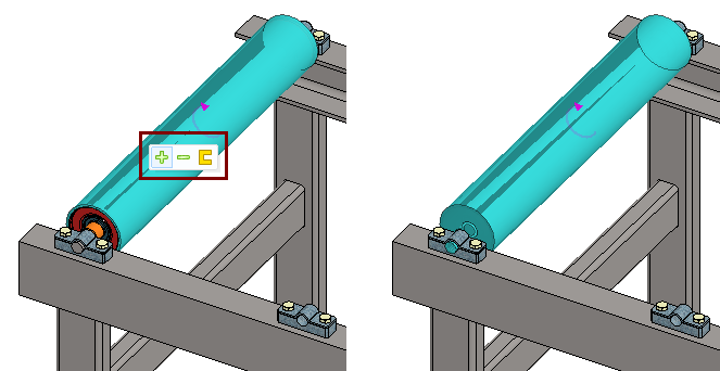
If you selected a roll by clicking to the roll geometry, only a part (eg roll shell) should be selected by default.
-
A mini-toolbar opens next to the cursor, allowing you to expand, collapse, or return to the original part selection.
-
The Plus button selects the next higher level assembly, etc.
-
The Minus button clears the selections one assembly level at a time.
-
The Part button returns to the selection of the original part.
Save the model and try the dimension table
-
File > Save or click


-
Right-click function: Dimension Table > Variables Only.
-
Old values: R_PCS 11 and R_GAP 400.
-
New values: R_PCS 11 and R_GAP 400.
-
Return to the old values.
-
If the number of rollers or locking pieces does not change, check that the patterns dealing with them have the above-mentioned variables in the Formula fields.
Try machining the screw holes in the U-beams
-
In the support piece (VX_AS5-P1) has a machining feature (red cylinder), whose length you can control using a dimension table.
-
If some part of the assembly includes a machining feature, or the entire part has the Tool properties, then you can find the right-click function: Machining features > Execute.
-
Try the above function.
-
Hide the locking pieces at once.
-
Click a pattern of locking pieces from the feature tree.
-
Hide selected parts with

-
-
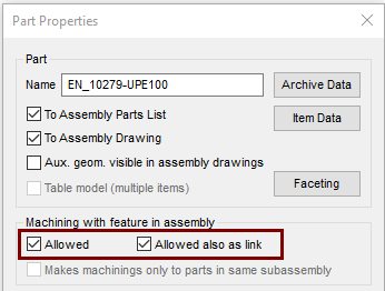
If no holes were created in the U-beam, then the properties of the U-beams should be changed.
In the part model, the machining feature is always displayed.
In the assembly model, the visibility of the machining feature is controlled by the 
You can save the part machined in the assembly as a new part:
-
Click the part (which has been machined).
-
Right-click function: Machining features > Save Machined as New.
-
Enter the Label for the part.
-
If you want to change or add the archive information of part, first open the part in a browser and then change the information. (that is, it is not possible to edit them during saving.)
Note that machining is not done on the original link model, but only on the geometry that appears in the assembly.
-
This is because the same (link) part may be involved in many assemblies, and it is not appropriate to apply machining to all assemblies.
If you should also work on the original link part, use the right-click function: Boolean and use the operation: Subtract with the tool.
Allow U-beam machining (if required)
-
In the main assembly, select the frame assembly VX_AS5-A2.
-
Right-click function: Edit.
-
Click the U-bar. (both in turn).
-
Right-click function: Properties.
-
Under Machining with feature in assembly: Select Allowed and Allowed also as link.
-
OK.
-
-
Return to the assembly: OK.
-
Right-click function: Machining features > Save Machined as New.
If you adjust the number of conveyor rollers using the dimension table or the conveyor frame is updated to the assembly, execute the machining features again.
Save the model and save it also to new model
-
File > Save or click
-
File > Save as New
-
Enter the label.
-
Enter the archive information by clicking Arc.Data.
-
Accept the same project.
-
OK.
-
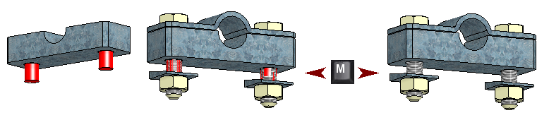
Replace the locking pieces with a bearing bracket
-
Select the first locking pieces of the pattern (VX_AS5-A3).
-
Right-click function: Change.
-
Select bearing bracket VX_AS5_UCP205B as a replacement part.
-
There is a valid selection in the Change Part dialog: Change this because the part being replaced is in series.
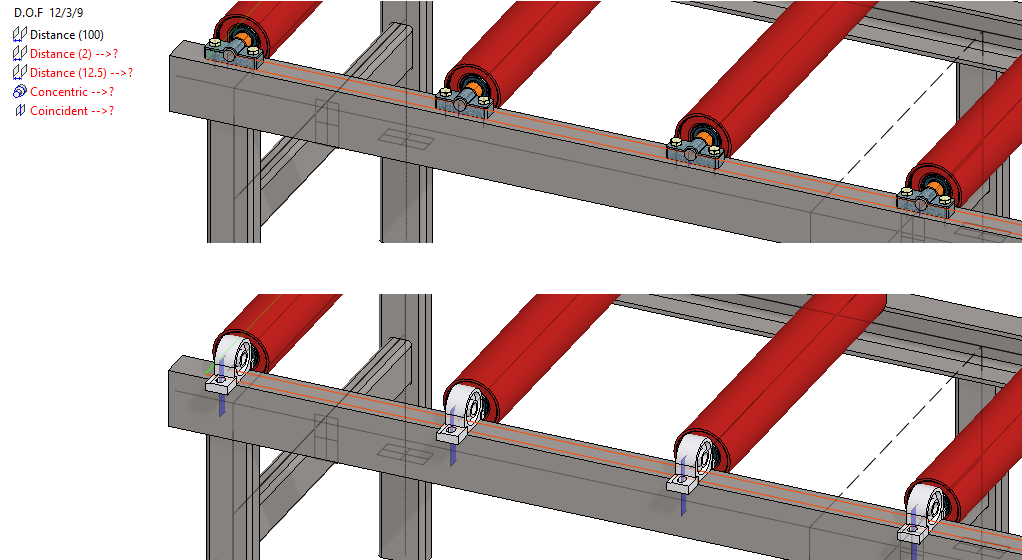
You will see that the bearing comes in the wrong position and the constraints associated with the locking pieces go red and no pair can be found for them.
-
The constraints will turn red if they are not come true.
-
The constraints are followed by the symbol ->, which means that there is no other party to the constraint (surface, line or point).
An alternative way to handle the replacement of the locking pieces into bearing brackets and the bearing roller into a fixed roller could be to remove both the existing rollers and locking pieces and first add the bearing bracket as a pattern and then a new conveyor roller as a pattern.
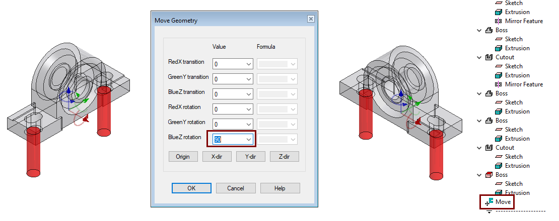
Turn the bearing to the correct position
-
Open the model VX_AS5_UCP204.
-
Right-click function: Edit Model > Move the whole geometry of part.
-
The Dialog Move Geometry opens.
-
-
In field BlueZ rotation enter: 90.
-
OK.
-
Save the model and remove it from the desktop.
The history step Move is created in the feature tree of part, which can be modified to change the position of the part again.
Return to assembly
-
Update the model with the

-
The program marks the changed parts on a red background in a feature tree.
-
-
Update changed parts with right-click function: Update All.
-
The bearings turn to the correct position, but most constraints are in red.
-
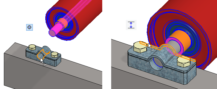
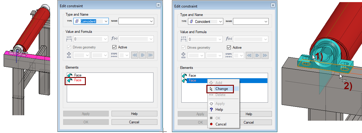
Edit the constraint, that is, reconnect it to the new face
-
Click the red coincident constraint (which affects the surface of the U-bar) from the list of constraints.
-
Right-click function: Edit.
-
Click the red element (Face).
-
Right-click function: Change.
-
Click to the part you were going to click to the face, in the figure 1).
-
Click on a face of the part, in the figure 2).
In the same style, you can edit other bad constraints.
-
At least modify the Concentric constraint by placing the concentricity on the bearing bracket.
-
Replace the previous Distance constraint12.5 from the outer surface of the U-beam to the outer surface of the bearing bracket 8.
Another option is to delete the constraints and re-add them.
Replace the bearing roller with a fixed roller
-
Select the first the conveyor roller assembly on the pattern (VX_AS5-A1).
-
Right-click function: Change.
-
Select the conveyor roller VX_AS5-A4 as the replacement part.
-
OK.
In this case, the Concentric constraint does not turn red. It is solely due to the fact that both conveyor rollers use the same shaft (VX_AS5-P3), so the counterparts (faces) are known.
-
Remove the previous distance constraint, 2, associated with the sleeve (both faces of constraint have been removed) and add distance constraint to the new conveyor roller sleeve and bearing.
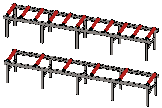
Edit the pattern of bearing brackets
-
In the feature tree, click the pattern that has the bearing brackets.
-
Right-click function: Edit.
-
Enter a new value for the Delta of Width-direction: 661
The bearing bracket is not symmetrical, so now the bearing bracket on the other side is in the wrong direction.
-
For this reason, replacing the locking pieces with bearing bearings was not the best solution.
-
A better solution would have been to bring the bearing bracket twice and turn the other into a mirror image and then make a series of both.
As of the main version 27.0.00 (Vertex 2021), parts in the series can be mirrored.
-
In this case, the bearing bracket could first be made in pattern on top of the first U-beam and then mirrored on the other side with respect to the Vertical (XZ) plane of the assembly.
Create a drawing for the model
-
See instructions for Modeling parts course exercise: 5 Drawing of model.
Save the model
-
File > Save or click
Download conveyor model with locking pieces here (VX_AS5.vxz)
Download conveyor model with bearing brackets here (VX_AS5B.vxz)