

Exercise 11: Cross Section
This exercise was carried out with version 27.0 (Vertex 2021).
In this exercise you will learn to
-
To sketch cross sections of profiles.
-
To save the cross section in the profile library.
-
Sweeping a profile-type library feature along a guide line.
-
Cut out the sketch lines.
Functions to be used:
-
New Sketch > To horizontal (XY) plane.
-
Sketching: Two point rectangle, Two Point Line, Circle with Center and Radii Point and Acr with Tree Points.
-
Sketching constraints: Distance, Symmetry, Tangential and Diameter.
-
Sketching: Delete Section of Line.
-
Operation: Guide curve.
-
Operation: Cross Section.
-
Part: Sweep.
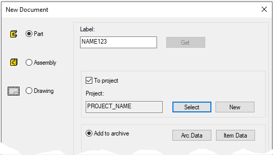
Create a new part
-
File > New > Part.
-
Enter the label (which is also the name of the model and by default will be the name of the drawing).
-
Enter the archive information by clicking Arc.Data.
-
Select the project for model.
-
OK.
-
Create the only sketch of the model
-
New Sketch > To horizontal (XY) plane.
-
Line style: Guide line.
-
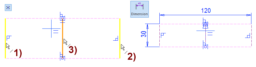
Sketch a rectangle.
-
Sketch a line segment. (Two point line)
-
Use the midpoints of the lines as the start and end points of the segment.
-
-
The model may have only one history stage, i.e. one sketch.
-
The sketch must be made to Horizontal (XY) plane.
-
No handle is added to the model, such as for features or components to be saved in library.
Note that the default placement point for the cross-section added from the library is the origo of the sketch.
-
The placement point can be changed when performing a sweep.
The lines above could also be Constructional, in which case they would not appear in the model or in the feature retrieved from the library.
It is a good idea to define guide lines as lines that can be used (also endpoints) can be used when positioning a cross-sectional feature in a sweep or in profile structure design relative to a guide curve.
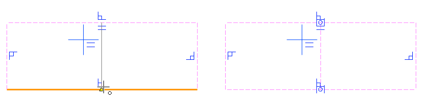
Add a symmetry constraint and main dimensions
-
Add a symmetry constraint for the vertical lines with respect to the vertical line of the center cross.
-
Give the width and height dimensions.
If the origo is outside the rectangle, drag the rectangle so that the origo is inside.
Sketch and position the circles
-
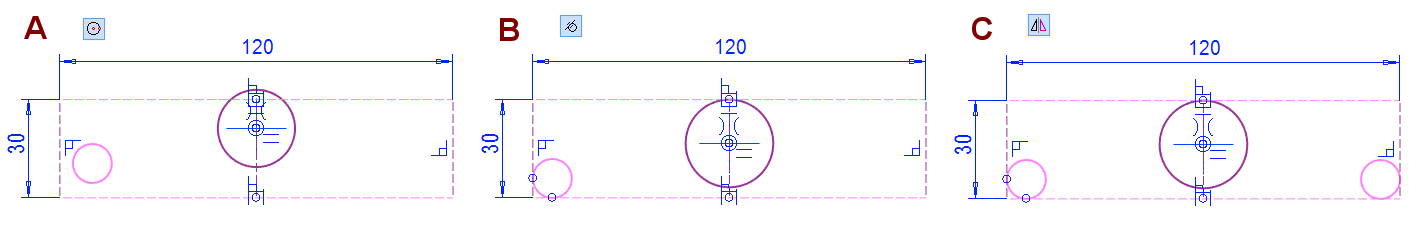
Sketch two circles, in the figure A.
-
The second circle so that its center is attached to the origo.
-
-
Add tangential constraint to the circles, in the figure B.
-
Left circle tangential to the lower horizontal line and the left vertical line.
-
The circle of origo tangential to the upper horizontal line.
-
-
Mirror the left circle with respect to the vertical axis of the center cross, in the figure C.
Sketch and place the arc, add the equal radius constraint to the circles
-
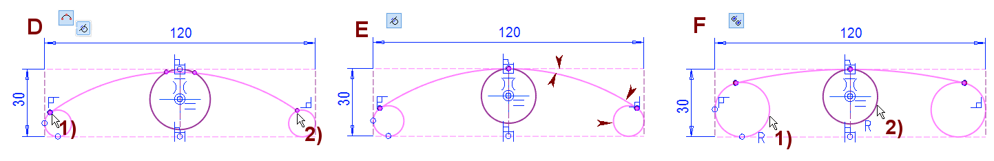
Sketch Arc with three Points, in the figure D.
-
Note that the tangentiality (mini toolbar) is selected with the arc drawing.
-
Click the left circle.
-
Click the right circle.
-
-
Add tangential to the arc, in the figure E.
-
Click to the arc and top guide line.
-
Click the arc and the circle on the right.
-
-
Add the Equal Radius constraint between two circles, in the figure F.
Add offset arc, inner circles, and tangential constraint.
-
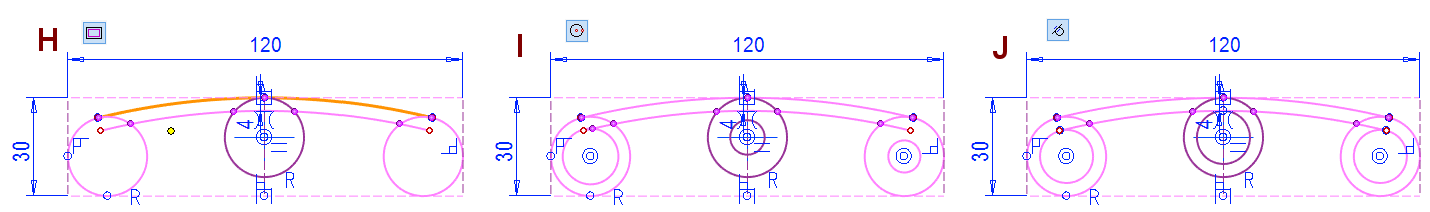
Add an offset line to the arc 4mm inside, in the figure H.
-
Sketch three circles, in the figure I.
-
Click to the location of the center of the circle from the center of the old circles.
-
-
Add a tangential constraint to these circles and the inner arc, in the figure J.
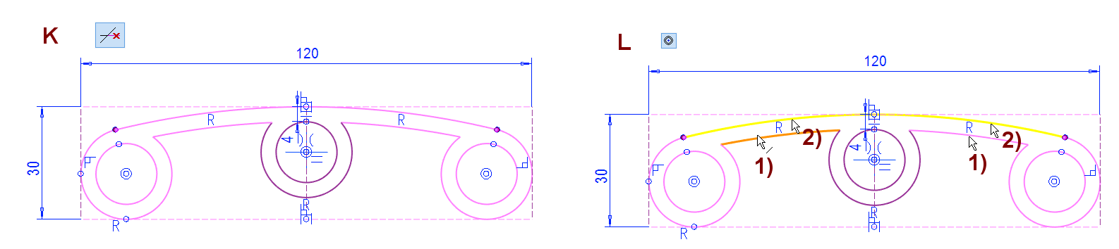
Cut out extra line sections and add a concentricity constraint.
-
Remove extra sections from the lines, in the figure K.
-
Function: Delete Section.
-
-
Add Concentricity constraint to arcs, in the figure L.
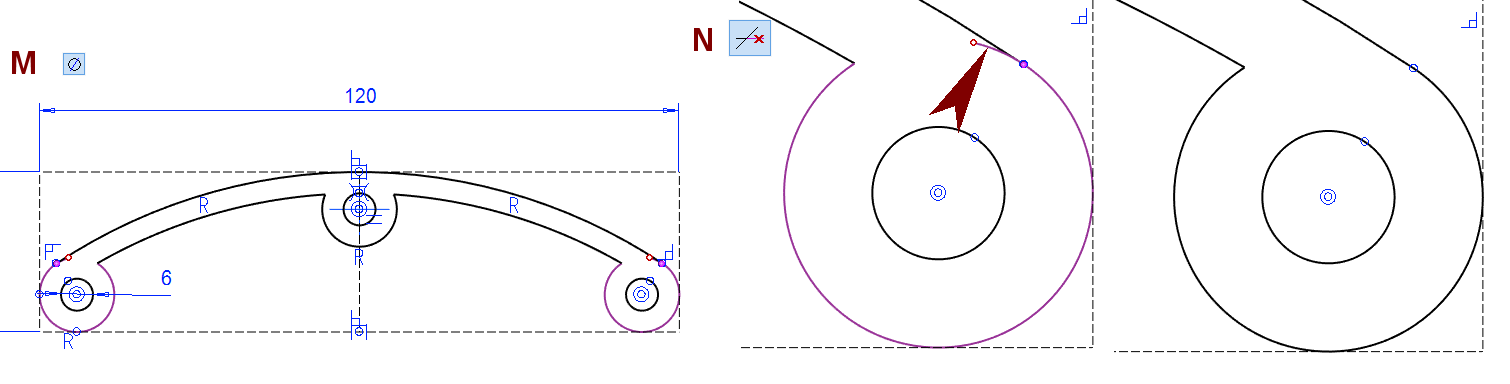
Add a diameter constraint and check the sketch
-
Add a Diameter constraint for one circle, in the figure M.
-
If the there is open line endpoints in the sketch (red dot), edit the sketch.
-
The arc is too long, in the figure N.
-
Use Function: Delete Section.
-
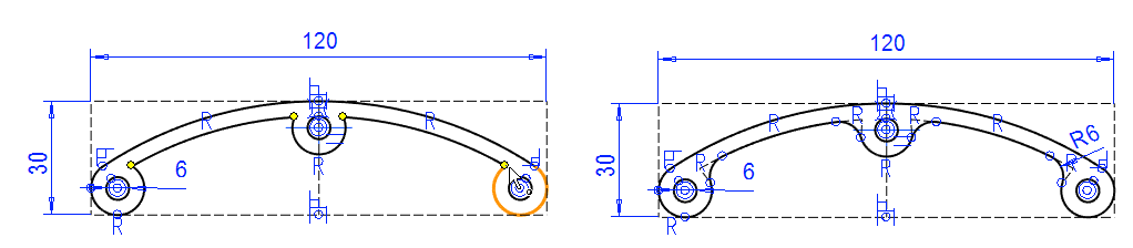
Add roundings to sharp corners
-
Click four points (Use Crtl key when selecting).
-
Right-click function: Round.
-
Enter: 6.
-
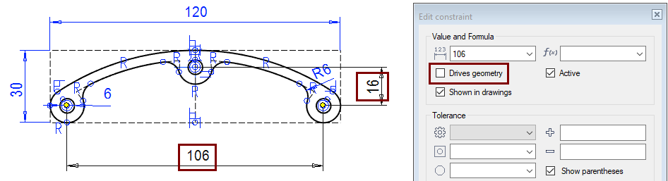
Check the distance between the holes
-
Add a Dimension (or distance condition) between the center of circles, remember to deselect: Drives geometry.
-
If the dimension drives geometry, then the sketch is overdefined.
-
Dimensions do not modify the geometry.
-
But they can serve as inspection dimensions
-
And they assist the designer by showing the dimensions needed elsewhere.
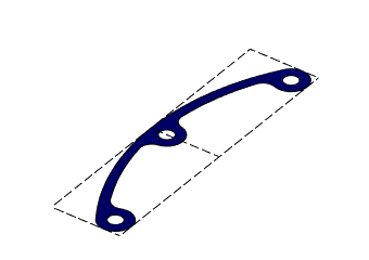
Perform the Cross Section operation
-
Stop sketching (the green OK button).
-
Select: Cross Section.
-
Click OK.
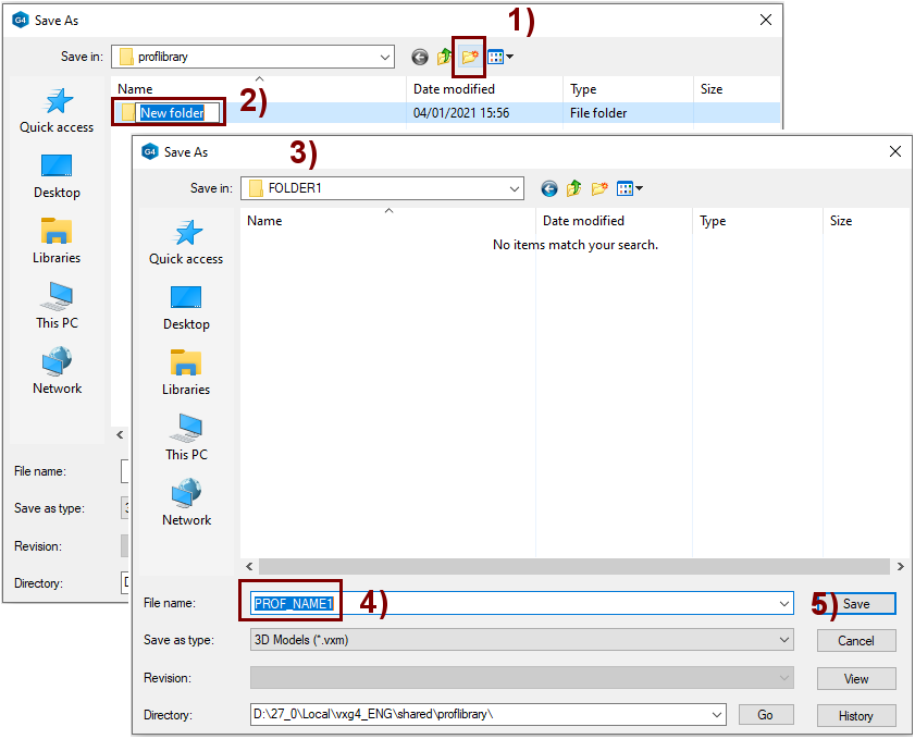
Save the cross section to the library
-
Right-click function: Save to Library > As Profile.
-
Select a folder or create a new folder.
-
It's a recommended to save Cross Section (= Profile) of the same type in the same folder.
-
-
Create a new folder, in the figure 1).
-
Enter a name for the folder, in the figure 2).
-
Select the folder, in the figure 3).
-
Enter the name for profile, in the figure 4).
-
Save the profile, in the figure 5).
Save the model
-
File > Save or click


Create a new part
-
File > New > Part.
-
Enter the label (which is also the name of the model and by default will be the name of the drawing).
-
Enter the archive information by clicking Arc.Data.
-
Select the project for the model.
-
OK.
-
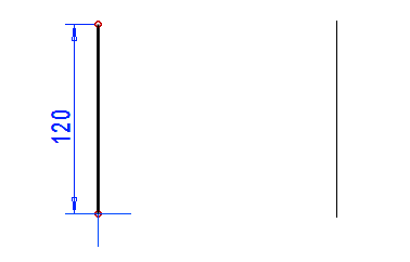
Model guide line
Create a sketch in a vertical plane
-
New Sketch > To Vertical (XZ) plane
-
Sketch a vertical line: A Two Point Line.
Operation:
-
Guide curve
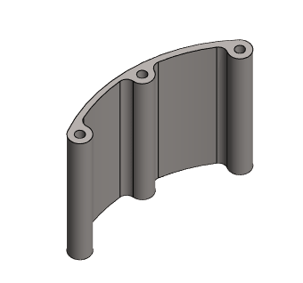
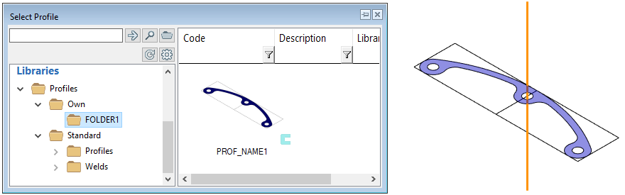
Create a part from the cross section and the guide line
-
Function: Add boss using cross-section from library.

-
Select a feature from the library: Profiles > Own > folder > profile (In this exercise FOLDER1 > PROF_NAME1)
-
Double-click the feature or
-
Grab it and drag it a little.
-
-
Place the cross section on the line.
-
The program goes to sketching mode, and you could use constraints to place the sketch.
-
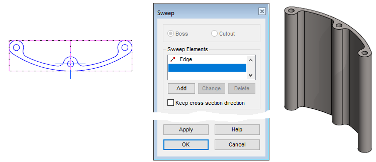
Complete the sweep
-
Exit sketch: OK.
-
The program presents the sweep information.
-
Now you could provide other information to guide the sweep.
-
-
OK: Perform a sweep.
Save the model
-
File > Save or click
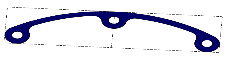
Examples
Below there is an example where the above cross-section has been used, but the guide curve is different.
Download the Cross Section model (VX_LN11.vxz) here.
Download here a model where the cross section has been used to form the part (VX_LN11A.vxz)